Download
1 / 17
170 likes | 286 Vues
Positron Source Relocation Damping Ring @ 10Hz S. Guiducci (INFN-LNF). BAW2, SLAC Tuesday 18 January 2011. Positron emittance damping. t/ x,y. e +. ~8 damping times are needed for the vertical emittance. 5 Hz x,y 26 ms 10 Hz x,y 13 ms. Electron emittance damping.

E N D
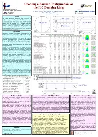
Positron Source RelocationDamping Ring @ 10Hz S. Guiducci (INFN-LNF) BAW2, SLAC Tuesday 18 January 2011
Positron emittance damping t/x,y e+ ~8 damping times are needed for the vertical emittance 5 Hz x,y 26 ms 10 Hzx,y 13 ms
Electron emittance damping t/x,y e- ~5 damping times are needed for the vertical emittance 5 Hz x,y 36 ms 10 Hzx,y 18 ms
SB2009 - 3.2 km ring DR Parameters for positron ring 8 damping times needed to reduce vertical e+ emittance 5 Hz x,y 26 ms 10 Hzx,y 13 ms Increase wiggler field Reduce wiggler period Increase the number of RF cavities
Cost related modifications RF voltage 7.513.4 MV Beam power 1.8 3.3 MW N. of RF cavities 6 9 Wiggler field1.62.4 T Wiggler period0.40.28 m Wiggler length 2.451.72 m N. of wigglers 3244 Total wig. sect. length 136176 m SR power per wiggler4063 kW
Comments on wiggler modifications • Some engineering design work is needed • Lattice and dynamic aperture tuning • SR copper absorbers* (not included in RDR costs) 0.5 m long, 40 kW; with modified wigglers there is space to increase the length to 0.75 m to absorb 60 kW • The SR power passing through all modules and continuing downstream to the fist arc dipole is 256 kW. This is expected to by ~ 1.5. A solution is to leave some space for more absorbers • Cryogenic load to be reevaluated *O. B. Malyshev, et al. “Mechanical and Vacuum Design of the Wiggler Section of the ILC Damping Rings”, ID: 2596 - WEPE092, IPAC10
Wiggler Photon Stop Issues • In consultation with Yulin Li & Xianghong Liu • 10 Hz Operation • Higher power load in each wiggler requires adjustments to design • Expect that a technical solution is possible • Alternating 10Hz Cycle Operation • Average power load is lower than previous case a no issues for cooling system • Rapid cycling will lead to added thermal stress at the photon absorbing surfaces • Some concern about ability of standard tools to model this (optimized for steady state calculations) • General recommendation is to provide additional operating margin relative to the steady state yield point • Assuming that baseline design is for full duty cycle 10Hz operation, the factor of 2 reduction in average power load likely satisfies the previous recommendation. • Conclusion: No serious issues are likely June 23, 2010 ILC ADI Meeting Mark Palmer 8
RF issues for pulsed beam operation Alessandro Gallo (INFN-LNF) Sergey Belomestnykh (BNL) See also Damping rings RF session at IWLC10, CERN October 2010: S. Belomestnykh, RF system issues due to pulsed beam in ILC DR, slides K. Kubo, Transient beam loading correction at ILC DR, slides
RF system parameters Main constrains 10 Hz beam repetition rate, 50 ms beam on/off time, ~1 ms injection/extraction time to fill/empty the ring Available klystron power: ~ 1 MW RF window power handling
The RF power in the presence of beam can be expressed as RF power demand (1) where b >> 1 is the coupling factor, QL is the cavity loaded quality factor, 0 is the beam phase relative to the crest of RF wave (a.k.a. synchronous phase), y is the cavity tuning angle. The first term includes active part of beam loading (due to particle energy loss), the second term includes reactive beam loading. The latter is usually compensated in real time by appropriate cavity detuning with a mechanical tuner so that the second term in square brackets is always zero. And then for maximum beam current and optimal quality factor the power demand is simply equal to the beam power per cavity (364 kW).
However, it is not possible to tune the cavity mechanically fast enough to compensate reactive portion of the beam loading during injection (~1 ms). For the DR parameters we get RF power demand (2) and, assuming that the cavity detuning is fixed and properly set to compensate the maximum beam current, the power demand when the beam is ejected becomes: • which does not exceed the power available from the klystron but, being fully reflected from the cavity, generates standing wave pattern and thusmay potentially create a power handling problem for an RF window/coupler and transmission line.
Cavity operation at fixed detuning. Case η ≤ 2 The optimization of the parameter set for the operation of a cavity at fixed tuning has been studied analytically. The best efficiency is obtained setting the input coupling and the detuning at the values matching the maximum current value expected in operation: Under this conditions the system is maximally mismatched at Ib=0. The RF power necessary to sustain the cavity fields at the required level is given by: where h is the overvoltage factor. One can see that for h ≤ 2 the cavities can be operated at fixed detuning while the power demand for zero beam current does not exceed the maximum beam power.
Cavity operation at fixed detuning. Case η ≥ 2 The forward RF power for generic values of input coupling Qext and cavity tuning angle ψ is given by: • At η ≥ 2 a generator power Pgen larger than the maximum beam power is required at Ib=0. This suggest to optimize the 2 free parameters Qext and ψ to fulfill the 2 conditions: Power equalization at the range edges Power minimization
Cavity operation at fixed detuning. Case η ≥ 2 (cnt’d) • Through some mathematics, optimal values of Qext and ψ are obtained: • Optimal choice of Qext and ψ parameters allows limiting the required generator power overhead. • For instance, it is possible to run the system with an overvoltage factor η = 3 at the cost of only 12.5 % of increased RF power.
First Robinson limit and direct RF feedback cure • A fixed tuning working point is potentially unstable with respect to the Robinson first limit (decrease of the coherent frequency for barycentric synchrotron oscillations). The ratio between coherent and incoherent synchrotron frequencies is given by: • = cavity impedance imaginary part sampled at the synchrotron sidebands around the RF harmonics • Direct RF feedback connection can be used to reduce the effective impedance imaginary parts, limiting the frequency shift. • Impedance reduction of two orders of magnitude can be obtained (negligible frequency shift)
Conclusions • 10 Hz operation of the ILC Damping Ring RF system seems to be feasible. • Cavity operation at fixed tuning is the most easily implementable configuration. No extra RF power is required for overvoltage factors η lower than 2, while optimal choice of the coupling and tuning parameters allow working up to η = 3 with modest RF power increase. Common concerns & studies needed: • RF window/coupler power handling with full reflection • Feedforward to mitigate transients during beam injection/extraction • Pulsed operation of the RF system is worth considering as it will save power and reduce thermal load on RF window/coupler. Two options here: (i) pulsed RF and klystron mod anode; (ii) pulsed klystron HV.