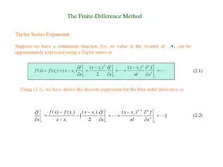
Download
1 / 23
230 likes | 334 Vues
A new phase difference compensation method for elliptically birefringent media. P iotr Kurzynowski, S ławomir Drobczyński Institute of Physics Wrocław University of Technology Poland. Scheme of presentation. The literature background Compensators for linearly birefringent media

E N D
A new phase difference compensation method for elliptically birefringent media Piotr Kurzynowski, Sławomir Drobczyński Institute of Physics Wrocław University of Technology Poland
Scheme of presentation • The literature background • Compensators for linearly birefringent media • Elliptically birefringent medium in the compensator setup • A phase plate eliminating the medium ellipticity • Numerical calculations • The measurement procedure • Experimental results • Conclusions
The literature background • H.G. Jerrard, „Optical Compensators for Measurements of Elliptical Polarization”, JOSA, Vol.38 (1948) • H. De Senarmont, Ann. Chim. Phys.,Vol.73 (1840) • P. Kurzynowski, „Senarmont compensator for elliptically birefringent media”, Opt. Comm., Vol.171 (2000) • J. Kobayashi, Y. Uesu, „A New Method and Apparatus ‘HAUP’ for Measuring Simultaneously Optical Activity and Birefringence of Crystals. I. Principles and Constructions”, J.Appl. Cryst., Vol.16 (1983) • C.C. Montarou, T.K. Gaylord, „Two-wave-plate compensator for single-point retardation measurements”, Appl. Opt., Vol.43 (2004) • P.Kurzynowski, W.A. Woźniak, „Phase retardation measurement in simple and reverse Senarmont compensators without calibrated quarter wave plates”, Optik, Vol.113 (2002) • M.A. Geday, W. Kaminsky, J.G. Lewis, A.M. Glazer, „Images of absolute retardance using the rotating polarizer method”, J. of Micr., Vol.198 (2000)
Direct compensators for linearly birefringent media A A=90 C=-45 x-variable M f=45 -unknown P P=0
The phase shift compensation ideafor direct compensators • A rule: the total phase shift introduced by two media is equal to the difference phase shifts introduced by the medium M and the compensator C, because • Transversal compensators (e.g. the Wollastone one): for some x0 co-ordinate axis • Inclined compensators (e.g. the Ehringhause one): for some inclination angle 0
Azimuthal compensators for linearly birefringent media A A-variable A0=90 /4 =0 M f=45 -unknown P P=0
The phase shift compensation idea for azimuthal compensators • A rule: the quarterwave plate transforms the polarization state of the light after te medium M to the linearly one:
Linearly birefringent medium in the compensator setup the Stokes vector V of the light after the medium M the light azimuth angle doesn’t change; the light ellipticity angle is equal to the half of the phase shift introduced by the medium M
Elliptically birefringent medium in the compensator setup (1) the Stokes vectorVof the light after the medium M but This is a rotation matrix R(2f) !
Elliptically birefringent medium in the compensator setup (2) hence so
Elliptically birefringent medium in the compensator setup (3) • elimination of the f medium M ellipticity influence • the rotation matrix • the rotation matrix a linearly birefringent medium C with the azimuth angle =0° and introducing the phase shift • so if the medium C is introduced in the setup, the light azimuth angle doesn’t change if only =2·f
Proposed compensator setups • for direct compensators: • for azimuthal compensators:
The direct compensation setup A A=90 C=-45 C-variable C=0 -variable M f=45 ,f unknown P P=0
The azimuthal compensation setup A A-variable A0=90 /4 =0 C=0 -variable M f=45 ,f unknown P P=0
The output light intensity distribution wherefor direct compensators or for azimuthal ones. generally where and
Numerical calculations--the Wollastone compensator setup • The normalized intensity distribution for i = - 2f 1= 0 <2<3
Numerical calculations--the Wollastone compensator setup • The normalized intensity distribution for = - 2f0
Numerical calculations--the Wollastone compensator setup • The normalized intensity distribution for = - 2f=0
The measurement procedure • The direct compensators: • the ellipticity angle fmeasurement the inclined (for example Ehringhause one) compensator C action the fringe visibility maximizing f b) the absolute phase shift measurement two-wavelength or white-light analysis of the intensity light distribution at the setup output
The Senarmont configuration • Two or one compensating plates? • A quarterwave plate action is from mathematically point of wiev a rotation matrix R(90°) • So symbolically • The new Senarmont setup configuration!
Experimental results (1) 1 < 2 < 3
Conclusions • Due to the compensating plate Capplication there is possibility to measure in compensators setups not only the phase shift introduced by the medium but also its ellipticity • The solution (,f) is univocal independently of medium azimuth angle f sign (±45°) indeterminity • A new (the last or latest?) Senarmont compensator setup has been presented