Download
1 / 82
820 likes | 1.11k Vues
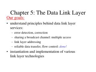
Our goals: understand principles behind data link layer services: error detection, correction sharing a broadcast channel: multiple access link layer addressing reliable data transfer, flow control: done! instantiation and implementation of various link layer technologies.

E N D
Our goals: understand principles behind data link layer services: error detection, correction sharing a broadcast channel: multiple access link layer addressing reliable data transfer, flow control: done! instantiation and implementation of various link layer technologies Chapter 5: The Data Link Layer
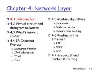
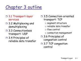
5.1 Introduction and services 5.2 Error detection and correction 5.3Multiple access protocols 5.4 LAN addresses and ARP 5.5 Ethernet 5.6 Hubs, bridges, and switches 5.7 Wireless links and LANs 5.8 PPP Chapter 5 outline
Some terminology: hosts and routers are nodes (bridges and switches too) communication channels that connect adjacent nodes along communication path are links wired links wireless links LANs 2-PDU is a frame,encapsulates datagram “link” Link Layer: Introduction data-link layer has responsibility of transferring datagram from one node to adjacent node over a link
Datagram transferred by different link protocols over different links: e.g., Ethernet on first link, frame relay on intermediate links, 802.11 on last link Each link protocol provides different services e.g., may or may not provide rdt over link transportation analogy trip from Princeton to Lausanne limo: Princeton to JFK plane: JFK to Geneva train: Geneva to Lausanne tourist = datagram transport segment = communication link transportation mode = link layer protocol travel agent = routing algorithm Link layer: context
Link Layer Services • Framing, link access: • encapsulate datagram into frame, adding header, trailer • channel access if shared medium • ‘physical addresses’ used in frame headers to identify source, dest • different from IP address! • Reliable delivery between adjacent nodes • we learned how to do this already (chapter 3)! • seldom used on low bit error link (fiber, some twisted pair) • wireless links: high error rates • Q: why both link-level and end-end reliability?
Link Layer Services (more) • Flow Control: • pacing between adjacent sending and receiving nodes • Error Detection: • errors caused by signal attenuation, noise. • receiver detects presence of errors: • signals sender for retransmission or drops frame • Error Correction: • receiver identifies and corrects bit error(s) without resorting to retransmission • Half-duplex and full-duplex • with half duplex, nodes at both ends of link can transmit, but not at same time
link layer implemented in “adaptor” (aka NIC) Ethernet card, PCMCI card, 802.11 card sending side: encapsulates datagram in a frame adds error checking bits, rdt, flow control, etc. receiving side looks for errors, rdt, flow control, etc extracts datagram, passes to rcving node adapter is semi-autonomous link & physical layers frame frame Adaptors Communicating datagram rcving node link layer protocol sending node adapter adapter
5.1 Introduction and services 5.2 Error detection and correction 5.3Multiple access protocols 5.4 LAN addresses and ARP 5.5 Ethernet 5.6 Hubs, bridges, and switches 5.7 Wireless links and LANs 5.8 PPP Chapter 5 outline
Error Detection • EDC= Error Detection and Correction bits (redundancy) • D = Data protected by error checking, may include header fields • Error detection not 100% reliable! • protocol may miss some errors, but rarely • larger EDC field yields better detection and correction
Parity Checking Two Dimensional Bit Parity: Detect and correct single bit errors Single Bit Parity: Detect single bit errors 0 0
Sender: treat segment contents as sequence of 16-bit integers checksum: addition (1’s complement sum) of segment contents sender puts checksum value into UDP checksum field Receiver: compute checksum of received segment check if computed checksum equals checksum field value: NO - error detected YES - no error detected. But maybe errors nonetheless? More later …. Internet checksum Goal: detect “errors” (e.g., flipped bits) in transmitted segment (note: used at transport layer only)
Checksumming: Cyclic Redundancy Check • view data bits, D, as a binary number • choose r+1 bit pattern (generator), G • goal: choose r CRC bits, R, such that • <D,R> exactly divisible by G (modulo 2) • receiver knows G, divides <D,R> by G. If non-zero remainder: error detected! • can detect all burst errors less than r+1 bits • widely used in practice (ATM, HDCL)
CRC Example Want: D.2r XOR R = nG equivalently: D.2r = nG XOR R equivalently: if we divide D.2r by G, want remainder R D.2r G R = remainder[ ]
5.1 Introduction and services 5.2 Error detection and correction 5.3Multiple access protocols 5.4 LAN addresses and ARP 5.5 Ethernet 5.6 Hubs, bridges, and switches 5.7 Wireless links and LANs 5.8 PPP Chapter 5 outline
Multiple Access Links and Protocols Two types of “links”: • point-to-point • PPP for dial-up access • point-to-point link between Ethernet switch and host • broadcast (shared wire or medium) • traditional Ethernet • upstream HFC • 802.11 wireless LAN
Multiple Access protocols • single shared broadcast channel • two or more simultaneous transmissions by nodes: interference • only one node can send successfully at a time multiple access protocol • distributed algorithm that determines how nodes share channel, i.e., determine when node can transmit • communication about channel sharing must use channel itself! • what to look for in multiple access protocols:
Ideal Mulitple Access Protocol Broadcast channel of rate R bps 1. When one node wants to transmit, it can send at rate R. 2. When M nodes want to transmit, each can send at average rate R/M 3. Fully decentralized: • no special node to coordinate transmissions • no synchronization of clocks, slots 4. Simple
MAC Protocols: a taxonomy Three broad classes: • Channel Partitioning • divide channel into smaller “pieces” (time slots, frequency, code) • allocate piece to node for exclusive use • Random Access • channel not divided, allow collisions • “recover” from collisions • “Taking turns” • tightly coordinate shared access to avoid collisions
CSMA (Carrier Sense Multiple Access) CSMA: listen before transmit: • If channel sensed idle: transmit entire frame • If channel sensed busy, defer transmission • Human analogy: don’t interrupt others!
CSMA/CD (Collision Detection) CSMA/CD: carrier sensing, deferral as in CSMA • collisions detected within short time • colliding transmissions aborted, reducing channel wastage • collision detection: • easy in wired LANs: measure signal strengths, compare transmitted, received signals • difficult in wireless LANs: receiver shut off while transmitting • human analogy: the polite conversationalist
“Taking Turns” MAC protocols channel partitioning MAC protocols: • share channel efficiently and fairly at high load • inefficient at low load: delay in channel access, 1/N bandwidth allocated even if only 1 active node! Random access MAC protocols • efficient at low load: single node can fully utilize channel • high load: collision overhead “taking turns” protocols look for best of both worlds!
“Taking Turns” MAC protocols Token passing: • control token passed from one node to next sequentially. • token message • concerns: • token overhead • latency • single point of failure (token) Polling: • master node “invites” slave nodes to transmit in turn • concerns: • polling overhead • latency • single point of failure (master)
Summary of MAC protocols • What do you do with a shared media? • Channel Partitioning, by time, frequency or code • Time Division,Code Division, Frequency Division • Random partitioning (dynamic), • ALOHA, S-ALOHA, CSMA, CSMA/CD • carrier sensing: easy in some technologies (wire), hard in others (wireless) • CSMA/CD used in Ethernet • Taking Turns • polling from a central site, token passing
LAN technologies Data link layer so far: • services, error detection/correction, multiple access Next: LAN technologies • addressing • Ethernet • hubs, bridges, switches • 802.11 • PPP • ATM
LAN Addresses and ARP 32-bit IP address: • network-layer address • used to get datagram to destination IP network (recall IP network definition) LAN (or MAC or physical or Ethernet) address: • used to get datagram from one interface to another physically-connected interface (same network) • 48 bit MAC address (for most LANs) burned in the adapter ROM
LAN Addresses and ARP Each adapter on LAN has unique LAN address
LAN Address (more) • MAC address allocation administered by IEEE • manufacturer buys portion of MAC address space (to assure uniqueness) • Analogy: (a) MAC address: like Social Security Number (b) IP address: like postal address • MAC flat address => portability • can move LAN card from one LAN to another • IP hierarchical address NOT portable • depends on IP network to which node is attached
223.1.1.1 223.1.2.1 E B A 223.1.1.2 223.1.2.9 223.1.1.4 223.1.2.2 223.1.3.27 223.1.1.3 223.1.3.2 223.1.3.1 Recall earlier routing discussion Starting at A, given IP datagram addressed to B: • look up net. address of B, find B on same net. as A • link layer send datagram to B inside link-layer frame frame source, dest address datagram source, dest address A’s IP addr B’s IP addr B’s MAC addr A’s MAC addr IP payload datagram frame
Question: how to determine MAC address of B knowing B’s IP address? ARP: Address Resolution Protocol • Each IP node (Host, Router) on LAN has ARP table • ARP Table: IP/MAC address mappings for some LAN nodes < IP address; MAC address; TTL> • TTL (Time To Live): time after which address mapping will be forgotten (typically 20 min)
A wants to send datagram to B, and A knows B’s IP address. Suppose B’s MAC address is not in A’s ARP table. A broadcasts ARP query packet, containing B's IP address all machines on LAN receive ARP query B receives ARP packet, replies to A with its (B's) MAC address frame sent to A’s MAC address (unicast) A caches (saves) IP-to-MAC address pair in its ARP table until information becomes old (times out) soft state: information that times out (goes away) unless refreshed ARP is “plug-and-play”: nodes create their ARP tables without intervention from net administrator ARP protocol
Routing to another LAN walkthrough: send datagram from A to B via R assume A knows B IP address • Two ARP tables in router R, one for each IP network (LAN) • In routing table at source Host, find router 111.111.111.110 • In ARP table at source, find MAC address E6-E9-00-17-BB-4B, etc A R B
A creates datagram with source A, destination B • A uses ARP to get R’s MAC address for 111.111.111.110 • A creates link-layer frame with R's MAC address as dest, frame contains A-to-B IP datagram • A’s data link layer sends frame • R’s data link layer receives frame • R removes IP datagram from Ethernet frame, sees its destined to B • R uses ARP to get B’s physical layer address • R creates frame containing A-to-B IP datagram sends to B A R B
Ethernet “dominant” LAN technology: • cheap $20 for 100Mbs! • first widely used LAN technology • Simpler, cheaper than token LANs and ATM • Kept up with speed race: 10, 100, 1000 Mbps Metcalfe’s Ethernet sketch
Ethernet Frame Structure Sending adapter encapsulates IP datagram (or other network layer protocol packet) in Ethernet frame Preamble: • 7 bytes with pattern 10101010 followed by one byte with pattern 10101011 • used to synchronize receiver, sender clock rates
Ethernet Frame Structure (more) • Addresses: 6 bytes • if adapter receives frame with matching destination address, or with broadcast address (eg ARP packet), it passes data in frame to net-layer protocol • otherwise, adapter discards frame • Type: indicates the higher layer protocol, mostly IP but others may be supported such as Novell IPX and AppleTalk) • CRC: checked at receiver, if error is detected, the frame is simply dropped
Unreliable, connectionless service • Connectionless: No handshaking between sending and receiving adapter. • Unreliable: receiving adapter doesn’t send acks or nacks to sending adapter • stream of datagrams passed to network layer can have gaps • gaps will be filled if app is using TCP • otherwise, app will see the gaps
No slots adapter doesn’t transmit if it senses that some other adapter is transmitting, that is, carrier sense transmitting adapter aborts when it senses that another adapter is transmitting, that is, collision detection Before attempting a retransmission, adapter waits a random time, that is, random access Ethernet uses CSMA/CD
1. Adaptor gets datagram from and creates frame 2. If adapter senses channel idle, it starts to transmit frame. If it senses channel busy, waits until channel idle and then transmits 3. If adapter transmits entire frame without detecting another transmission, the adapter is done with frame ! 4. If adapter detects another transmission while transmitting, aborts and sends jam signal 5. After aborting, adapter enters exponential backoff: after the mth collision, adapter chooses a K at random from {0,1,2,…,2m-1}. Adapter waits K*512 bit times and returns to Step 2 Ethernet CSMA/CD algorithm
Ethernet Technologies: 10Base2 • 10: 10Mbps; 2: under 200 meters max cable length • thin coaxial cable in a bus topology • repeaters used to connect up to multiple segments • repeater repeats bits it hears on one interface to its other interfaces: physical layer device only! • has become a legacy technology
nodes hub 10BaseT and 100BaseT • 10/100 Mbps rate; latter called “fast ethernet” • T stands for Twisted Pair • Nodes connect to a hub: “star topology”; 100 m max distance between nodes and hub • Hubs are essentially physical-layer repeaters: • bits coming in one link go out all other links • no frame buffering • no CSMA/CD at hub: adapters detect collisions • provides net management functionality
Manchester encoding • Used in 10BaseT, 10Base2 • Each bit has a transition • Allows clocks in sending and receiving nodes to synchronize to each other • no need for a centralized, global clock among nodes! • Hey, this is physical-layer stuff!
Gbit Ethernet • use standard Ethernet frame format • allows for point-to-point links and shared broadcast channels • in shared mode, CSMA/CD is used; short distances between nodes to be efficient • uses hubs, called here “Buffered Distributors” • Full-Duplex at 1 Gbps for point-to-point links • 10 Gbps now !
5.1 Introduction and services 5.2 Error detection and correction 5.3Multiple access protocols 5.4 LAN addresses and ARP 5.5 Ethernet 5.6 Hubs, bridges, and switches 5.7 Wireless links and LANs 5.8 PPP Chapter 5 outline
Interconnecting LAN segments • Hubs • Bridges • Switches • Remark: switches are essentially multi-port bridges. • What we say about bridges also holds for switches!
Interconnecting with hubs • Backbone hub interconnects LAN segments • Extends max distance between nodes • But individual segment collision domains become one large collision domain • if a node in CS and a node EE transmit at same time: collision • Can’t interconnect 10BaseT & 100BaseT
Bridges • Link layer device • stores and forwards Ethernet frames • examines frame header and selectively forwards frame based on MAC dest address • when frame is to be forwarded on segment, uses CSMA/CD to access segment • transparent • hosts are unaware of presence of bridges • plug-and-play, self-learning • bridges do not need to be configured
collision domain collision domain bridge = hub = host LAN segment LAN segment Bridges: traffic isolation • Bridge installation breaks LAN into LAN segments • bridges filter packets: • same-LAN-segment frames not usually forwarded onto other LAN segments • segments become separate collision domains LAN (IP network)
Forwarding • How do determine to which LAN segment to forward frame? • Looks like a routing problem...
Self learning • A bridge has a bridge table • entry in bridge table: • (Node LAN Address, Bridge Interface, Time Stamp) • stale entries in table dropped (TTL can be 60 min) • bridges learn which hosts can be reached through which interfaces • when frame received, bridge “learns” location of sender: incoming LAN segment • records sender/location pair in bridge table
Filtering/Forwarding When bridge receives a frame: index bridge table using MAC dest address if entry found for destinationthen{ if dest on segment from which frame arrivedthen drop the frame else forward the frame on interface indicated } else flood forward on all but the interface on which the frame arrived