Download
1 / 15
351 likes | 847 Vues
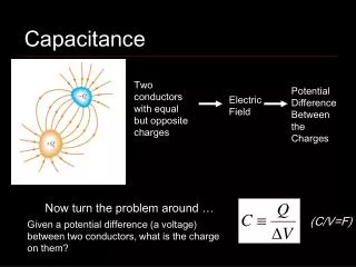
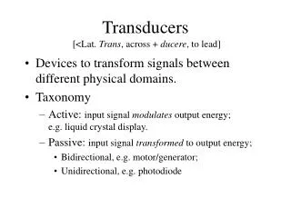
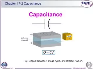
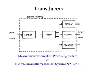
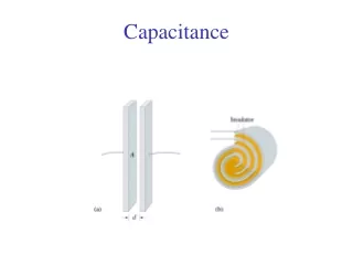
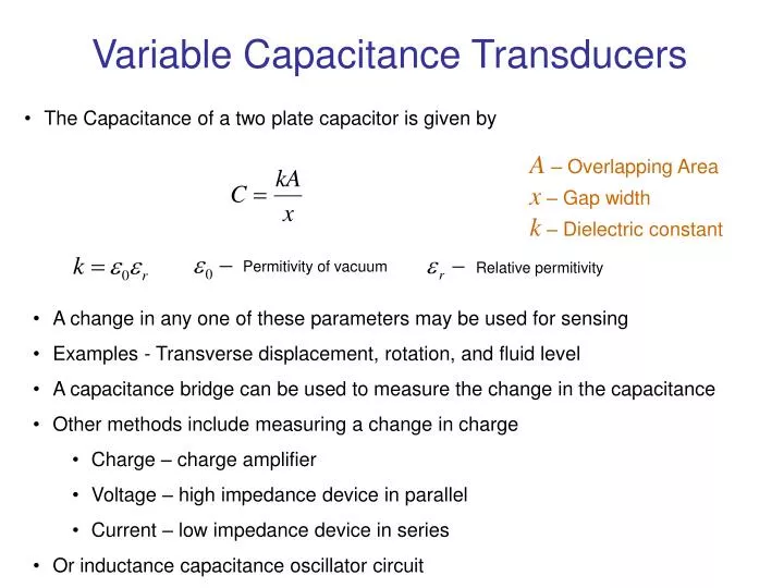
Variable Capacitance Transducers. The Capacitance of a two plate capacitor is given by. A – Overlapping Area x – Gap width k – Dielectric constant. Permitivity of vacuum. Relative permitivity. A change in any one of these parameters may be used for sensing

E N D
Variable Capacitance Transducers • The Capacitance of a two plate capacitor is given by A – Overlapping Area x – Gap width k – Dielectric constant Permitivity of vacuum Relative permitivity • A change in any one of these parameters may be used for sensing • Examples - Transverse displacement, rotation, and fluid level • A capacitance bridge can be used to measure the change in the capacitance • Other methods include measuring a change in charge • Charge – charge amplifier • Voltage – high impedance device in parallel • Current – low impedance device in series • Or inductance capacitance oscillator circuit
Capacitive Rotation Sensor • One plate rotates and the other is stationary • Common area is proportional to the angle • The relationship is linear and K is the sensor constant • Sensitivity is Capacitance Bridge DC Output vo Fixed Plate Rotation A θ Rotating Plate
Capacitive Displacement Sensor • One plate is attached to the moving object and the other is kept stationary • Capacitance is and sensitivity is • This relationship is nonlinear but can be linearized by using an op amp circuit C = K/x Capacitance Bridge vo Cref A − Supply Voltage vref + + + Fixed Plate Output vo Op amp Position x − Moving Plate (e.g., Diaphragm) −
Displacement Measurement by changing Dielectric • Displacement can be measured by attaching the moving object to a solid dielectric element placed in between the plates • Liquid level as shown below can be measured as the dielectric medium between the plates changes with the liquid level Capacitance Bridge vo Fixed Plate Liquid Level h k
R i + + Supply Voltage vref Output vo − − Displacement Measurement From phase From magnitude
i + Current Sensor + Supply Voltage vref − − Capacitive Angular Velocity Sensor
Capacitive Sensor Applications • Mechanical loading effects are negligible • Variations in dielectric properties due to humidity, temperature, pressure, and impurities can cause errors • Capacitance bridge can compensate for these effects • Sensitivity – 1pF per mm
Capacitance Bridge Circuit Compensator Z1 Sensor Z2 AC Excitation Bridge Output vo v vref + Z3 Z4 Bridge Completion Bridge output due to sensor change For a balanced circuit
Charge Source q Equivalent Capacitance C Piezoelectric Sensors • Substances such as BaTiO3 (barium titanate),SiO2 (quartz in crystalline), and lead zirconate titanate can generate an electric charge when subjected to stress (strain) • Applications include • Pressure and strain measuring devices • Touch screens • Accelerometers • Torque/Force sensors • Piezoelectric materials deform when a voltage is applied. Applications include • Piezoelectric valves • Microactuators and MEMS
Output impedance of a piezoelectric sensor is very high • It varies with the frequency ~MΩ at 100Hz Sensitivity • Charge sensitivity For a surface area A (pressure applied – stress) • Voltage sensitivity – change in voltage due to unit increment in pressure per unit thickness (d is the thickness) • k is the dielectric constant of the crystal capacitor
Piezoelectric Accelerometer Spring Direction of Sensitivity (Input) Inertia Mass Piezoelectric Element Output vo Electrodes • Inertia force caused by the acceleration produces a voltage • Light weight, high frequency response (1MHz) • High output impedance – small voltages ~1mV • High spring stiffness – natural frequency or resonant frequency is high (20kHz) • Useful frequency range – 5kHz
Resonance Accelerometer Signal (dB) Useful Range 1 20,000 5,000 Frequency (Hz) Frequency response curve of a piezoelectric accelerometer • Typical accelerometer sensitivities – 10 pC/g (pico Coulomb per gravity) or 5mV/g • Sensitivity depends on the piezoelectric properties and the way the inertia force is applied • Large mass would result in a large force and a large output signal but • Load the measurand • Lower the resonant frequency
Charge Amplifier Rf Cf A − vo/K K + + q Output vo C Cc − Charge Amplifier Piezoelectric Sensor Cable • Impedance matching • Reduce speed of charge leakage