Download
1 / 40
400 likes | 543 Vues
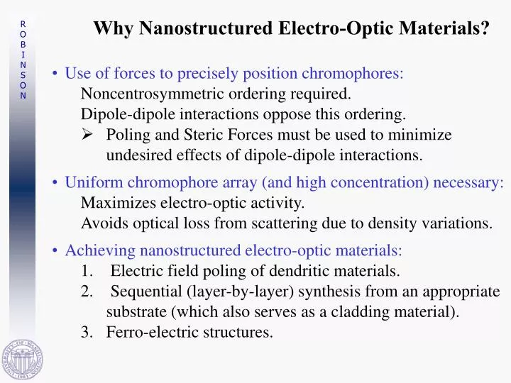
Why Nanostructured Electro-Optic Materials?. Use of forces to precisely position chromophores: Noncentrosymmetric ordering required. Dipole-dipole interactions oppose this ordering. Poling and Steric Forces must be used to minimize undesired effects of dipole-dipole interactions.

E N D
Why Nanostructured Electro-Optic Materials? • Use of forces to precisely position chromophores: Noncentrosymmetric ordering required. Dipole-dipole interactions oppose this ordering. • Poling and Steric Forces must be used to minimize undesired effects of dipole-dipole interactions. • Uniform chromophore array (and high concentration) necessary: • Maximizes electro-optic activity. • Avoids optical loss from scattering due to density variations. • Achieving nanostructured electro-optic materials: • Electric field poling of dendritic materials. • Sequential (layer-by-layer) synthesis from an appropriate substrate (which also serves as a cladding material). • Ferro-electric structures.
Levels of Theory: 1st Principles E & M Response and Properties Engineering Design Finite Element Analysis Process Simulation Segment Averages Group Additivities Solubilities Mesoscale Dynamics Equilibrium Properties Transport Properties Molecular Dynamics F=MA Quantum Mechanics H = E Force Field Charges years hours minutes Time seconds microsec nanosec picosec femtosec 1 Å 1 nm 10 nm micron mm meters Distance
Theoretically inspired rational improvement of organic electro-optic materials Theories (quantum and statistical mechanics) have guided the systematic improvement of the hyperpolarizability (b) of organic chromophores and the electro-optic activity of macroscopic materials.
Systematic Improvement in Molecular Electro-Optic Activity: Variation of mb
Hyperpolarizability (b) Driven by Quantum Mechanical Calculations of Molecules That Can Be Synthesized & Processed
Figure of Merit r eff mbin absence of intermolecular interactions
New Advances in Chromophore Development • Quantum mechanical calculations permit the optimization of the p-electron structure that defines molecular hyperpolarizability. • Microwave synthesis techniques permit dramatic enhancement in reaction yields and synthesis of new materials. . New Strategy: Gradient-Bridge, Mixed-Ligand-Acceptor Chromophores
Why Microwave Synthesis? •Microwave synthesis has permitted dramatic enhancement in reaction yields, reducing time devoted to purification. It has also permitted many materials to be synthesized for the first time and has permitted greater flexibility in reaction conditions. •Microwave synthesis techniques obviously permit more uniform heating of reaction mixtures. The absence of thermal gradients and “hot spots” helps minimize decomposition and side reactions. Microwave synthesis permits the use of a wider range of solvents. •We have found this approach to be particularly effective for condensation, addition, and de-protection reactions. .
Comparison of Microwave and Reflux Synthesis of CF3-TCF acceptor
Reducing Optical Loss Perfluorodendron-substituted Chromophore Contributes Little to Optical Loss in Guest-Host APC Polymer 0.85 dB/cm at 1.55 mm 0.68 dB/cm at 1.3 mm
Optimizing Photostability • Photochemical stability can be improved by chromophore design. Lumera has demonstrated this. • Photochemical stability can be improved by the use of scavengers .
Integrated WDM Transmitter Receiver Gold ground GND Au Electrode SU-8 Eye diagram 1 Gb/s, Vpeak = 1 V Device has ~2GHz BW = 2 GHz/V
Loading Evolution of N<cos3q> First Multi- Chromophore Dendrimer Simple Chromophore Shape Modification
Translating Microscopic to Macroscopic Electro-Optic Activity
Monte Carlo Calculations • Use Monte Carlo methods to determine the effect of dipolar interactions between chromophores. • Place dipoles on a grid (simple cubic lattice and body centered cubic lattice) • M by M by M array with r as nearest neighbor distance. A 5 by 5 two dimensional array Randomly oriented dipoles
How Monte Carlo Works • Choose a dipole • Rotate dipole by: a rotation axis and angle, selected randomly • Compare the energy before and after rotation. If the energy is higher, compare Boltzmann Probability with a [0,1] random number, and keep if larger. If the energy is lower, keep the move
Comparison of Potential Functions from Analytic Theory & Monte Carlo Calculations Points—Monte Carlo Calculation Solid Line—Analytic Theory .
Comparison of Theory & Experiment Experiment—Solid Diamonds .
Dendrimer Synthesis New Strategy: Generalize the Concept of Dendronized Chromophores. .
NLO Chromophre DMC3-97
Features of Ellipsoids • Complete flexibility of Charge and Dipole Distributions • Complete flexibility of Connectivity to other Ellipsoids • Complete flexibility of oreintation (for Monte Carlo and Brownian Dynamics Trajectories) • Polarizability Tensor • Computes all electrostatics with other Ellipsoids and arbitrary External Field • A contact function to find Ellipsoid-Ellipsoid interactions • Can have either Hard-Shell Repulsion or Leonard-Jones Interactions • Solvent free energies and exposure factors (use the rolling ball method) • Can generate dendrimers, polymers and lattices of ellipsoids
Dendrimer Performance By choosing a tilt angle for the three chromophores (~60°) the experimental enhancement (of ~ 2 fold) was realized. Statistical Mechanical Theory explains the improved performance of dendritic chromophores.
Dendrimer Structure Original Geometry
Three-Fold Dendrimer Three chromophores at Equilibrium With NO poling field: Nearly Planar
Three-Fold Dendrimer Three chromophores at Equilibrium With a poling field: Constrained and Aligned
Mission Possible Materials (I) The state of the art for OEO Materials: R33: 70 pm/V (CLD in 2000) Vp: 0.8 V (2000) R33: 130 pm/V (2002) Vp: 0.3 V (2000) Industry Standard: LiNiO3 R33: 32 pm/V Vp: 5 V (@40 GHz)
Mission Possible Materials (II) Quantum Mechanical Based Improvements: Increase b :Yes, by 5-10 fold Placement of Heteroatoms; Mix Donors and Acceptors Increase m: No, not needed Already 20 Debye and will go higher anyway Statistical Mechanical Based Improvements: Improve order by 5 fold (currently order is 5%) Design Dendrimers Improve Steric Interactions Place Chromophores on Polymer Backbone Improve order 20 fold FerroElectrically ordered materials • Only Theory can begin to crack this problem. • The new R33 is 130*20 = 2600 pm/V
Mission Possible Materials (III) Engineering Based Improvements: BandWidth: Done (100+ GHz performance now) Devices are cladding limited Design Devices to be in Resonant Structures (Trade Bandwidth for Vp) Use Photonic Band-Gap Structures to obtain beam confinement and minimize the need for cladding. (Theory can predict light beam confinement)