Download
1 / 31
310 likes | 479 Vues
Electro-optic techniques for bunch-length monitoring and synchronisation. Structure of talk: Brief summary of techniques Experiments at FELIX and FLASH Limitations and potential Other group activities Immediate future plans. Allan Gillespie Carnegie Laboratory of Physics

E N D
Electro-optic techniques for bunch-length monitoring and synchronisation Structure of talk: • Brief summary of techniques • Experiments at FELIX and FLASH • Limitations and potential • Other group activities • Immediate future plans Allan Gillespie Carnegie Laboratory of Physics University of Dundee
Dundee-Daresbury Diagnostic Group W.A. Gillespie (University of Dundee) P.J. Phillips (University of Dundee, ASTeC) A.M. MacLeod (University of Abertay Dundee) S.P. Jamison (ASTeC, Daresbury Laboratory) Collaborators: G. Berden, B. Redlich, A.F.G. van der Meer (FELIX) B. Steffen, E.-A. Knabbe, H. Schlarb, B. Schmidt, P. Schmüser (DESY)
E-O longitudinal bunch profile measurements F ~ ETHz Principle: Convert Coulomb field of e-bunch into an optical intensity variation Encode Coulomb field on to an optical probe pulse - fromTi:Sa or fibre laser v ≈ c electron bunch Decoding: via single-shot cross correlation in a BBO crystal propagating electric field(THz) yields the temporal intensity variations in a single laser pulse polariser chirped laser probe thin EO crystal ( FELIX & FLASH ) Detect polarisation rotation proportional to E or E2,depending on set-up
beam bunch Single-shot Temporal Decoding (EOTD) (gives best time resolution) Temporal profile of probe pulse→Spatial image of SHG pulse • stretched & chirped laser pulse leaving EO crystal assembly measured by short laser pulse via single-shot cross correlation in BBO • ~1mJ laser pulse energy required (Ti:Sa amplifier) OrSpectral Decoding(simpler) ... but suffers from artefacts at high frequencies
Improved time resolution ZnTe GaP Originally used ZnTe as E-O crystal – Latest FLASH measurements used GaP Possible improvements using different inorganic/organic materials .... ? electro-optic crystal response function • Temporal resolution fundamentally limited by : • crystal phonon resonance(s) • crystal dispersion • phase mismatch between Coulomb (THz) and laser (optical) fields
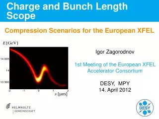
Benchmarking EO at FLASH against TDS (LOLA) cavity E = 450 MeV, q = 1nC~20% charge in main peak
EOTD experimental setup at DESY FLASH and some results with FLASH bunch compressors detuned Optimum compression Fitted Gaussian curve sigma = 79.3 ± 7.5 fs • 140m point on FLASH • beam energy 450 MeV • after LOLA TDC
Transverse deflecting cavity(destructive) EO temporal decoding (non-destructive) Physical Review Special Topics - Accelerators and Beams 12, 032802 (2009) [ Major review of the field with colleagues at FLASH and FELIX ] EO measurements of longitudinal bunch profile resolving sz ~ 60 fs (rms) bunch structure wakefields First ever detailed benchmarking (PRL 2007) of EO against aTransverse Deflecting System (TDS)
Vacuum Chamber Motorised Drive Camera Mirror and Crystal Assy Laser Exit Port EO compact probe head (FELIX) EO Technique is non-destructive and compact (requires 50 - 200 mm longitudinal space) electron beam ALICE version (Daresbury Laboratory, UK)
Range of Facilities used in EO measurements FELIX :FOM Institute ‘Rijnhuizen’, The Netherlands • - Coulomb field characterisation [PRL 2004]- Diagnostic capability tests using FEL radiation- single-shot EO measurements of CSR time profile • - Experimental EO Techniques FLASH :DESY, Hamburg • Coulomb field characterisation of electron bunches • First benchmarking against TDS (LOLA cavity) • ALICE : Daresbury, UK • - Coulomb field measurement / diagnostics development • Alpha-X : Strathclyde University, Glasgow, UK • Plasma Wakefield electron energy measurements, plus EO • Laser - Max Planck Institute for Quantum Optics, Garching • Wakefield: - University of Jena • - Central Laser Facility, Rutherford-Appleton Laboratory
Can we achieve even better resolution ...? • Coulomb angle limitation: 1/g ~ 50 fs for g ~ 1000 • Detector Material: • GaP • Move to new material? ( phase matching, (2) considerations ) • Could use GaSe, DAST, MBANP ..... or poled organic polymers? • Gate pulse width ~ 50 fs • Introduce shorter pulse • Use spectral interferometry • Use FROG Measurement (initially attempted at FELIX, 2004) • These methods will be tried on ALICE at Daresburyand other suitable facilities ...
Monitoring performance of bunch compression feedback system at FLASH Bunch compression switched off: Bunch compression switched on: Width of EOTD signal was 158 15 fs (fwhm) Width was 181 34 fs (fwhm)
Bunch arrival time monitoring at FLASH using EO setup Data taken with EO spectral decoding showing the arrival time of the electron bunch at the EO monitor station during SASE tuning in which the SASE output is optimised by changing the phase of the accelerator
Group planned use of Fibre Lasers in an Accelerator Environment • Fibre @ 1.55μm via SHG can generate 0.775 μm for seeding with Ti:Sa amplifier. Inherently low noise • Multiple fibre wavelengths allow experiments to be synchronised to accelerators. Clock distributed through stabilised fibres1 • Measurement of arrival time of electron bunch with EO techniques → bunch arrival time monitors (BAM @ FLASH)2 • Synchronisation to experiments in future accelerators – current state-of-art is ~30 fs over several hundred metres3 • Developing EO Fibre laser prototype with time resolution < 50 fs • FEL 2004 J. Kim et al • EPAC 2006 F. Loehl et al • 3 EPAC 2006 A. Winter et al
Rationale for migration of EO capability to fibre laser technology… • Robustness & reliability • Potential integration into accelerator timing system • Arrival time information for photon sources Erbium doped systems: 1.55 mm; likely timing distribution system. frequency doubled to 770nm => similar to Ti:Sa Ytterbium doped systems: 1030 nm: phase matched with GaP EO material Er system under construction at Daresbury Corresponding Yb system
ALICE - Accelerators and Lasers in Combined Experiments EO diagnostic test-station ... aiming for EO station up and running in July 2009
Experiments in progress / planned on ALICE Commissioning ALICE EO test-bed with Ti:S systems • temporal decoding ... signal-to-noise; pulse energy, ... • spectral decoding ... modified concepts for feedback • peak bunch current arrival-time monitoring (following FLASH) Tests of fibre EO system on ALICE • phase-matching • signal-noise • integration with fibre-laser timing distribution system Future Measurements • Synchronise fibre laser to ALICE RF • Phase noise measurements • Phase matching of Yb fibre with NL crystals • Optical bunch arrival time monitor
e- e- e- UV fs laser RF 10MW 20TW fs laser • RF Photoinjector • electron bunch production • 6.3 MeV, 100 fs, 100 pC Brookhaven N.L. T.U. Eindhoven LAL Orsay (Terry Garvey) • Wakefield Accelerator • e.g. capillary discharge waveguide • up to 1 GeV electrons U. Oxford (Simon Hooker) • Undulator • coherentradiation pulses • down to ~ 2 nm Daresbury Lab: ASTeC (Jim Clarke, Ben Shepherd) ALPHA-X Plasma Wakefield Project – Strathclyde University, Glasgow wakefield accelerator undulator photoinjector
ALPHA-X Beam Line Components 6.5 m high E focal plane low E focal plane YAG(Ce) screens 6.3MeV, 100-300fs bunches from gun EO bunch monitor (Dundee) electrons Broadband Electron Spectrometer (Dundee group)
Selected References: Free-electron laser pulse shape measurements with 100fs temporal resolution using a 10fs Ti:sapphire laser and differential optical gatingX.Yan, A.M. MacLeod, W.A.Gillespie et al. Nucl. Instr. Meths. Phys.Res. Vol A429 (1999) 7- 9Sub-picosecond electro-optic measurement of relativistic electron pulsesX. Yan, A.M. MacLeod, W.A. Gillespie, G.M.H. Knippels, D. Oepts, A.F.G. van der Meer. Physical Review Letters 85 (2000) 3404-7 Single-shot electron bunch length measurementsI. Wilke, A.M. MacLeod, W.A. Gillespie, G. Berden, G.M.H. Knippels, A.F.G. van der Meer Phys. Rev. Lett. 88 No 12 (2002) 124801/1-4 Real-time, non-destructive, single-shot electron bunch-length measurements G. Berden, S.P. Jamison, A.M .MacLeod, W.A. Gillespie, B. Redlich and A.F.G. van der Meer Physical Review Letters 93 (2004) 114802 Temporally resolved electro-optic effect S.P.Jamison, A.M. Macleod, G. Berden, D.A. Jaroszynski and W.A. Gillespie Optics Letters 31, 11 (2006) 1753-55 Benchmarking of Electro-Optic monitors for Femtosecond electron bunches G. Berden, W.A.Gillespie, S.P. Jamison, B. Steffen, V. Arsov, A.M. MacLeod, A.F.G. van der Meer, P.J. Phillips, H. Schlarb, B. Schmitt, and P. Schmüser Phys. Rev. Lett. 99 043901 (2007) Electro-optic time profile monitors for femtosecond electron bunches at the soft X-ray free-electron laser FLASH B. Steffen, V. Arsov, G. Berden, W.A. Gillespie, S.P. Jamison, A.M. MacLeod, A.F.G. van der Meer, P.J. Phillips, H. Schlarb, B. Schmitt, and P. Schmüser Physical Review Special Topics – Accelerators and Beams 12 032802 (2009)
In Summary ... • EO longitudinal profile capabilities approaching expected requirements • Has proven capability at ~60fs rms at ~450MeV • Capability is maintained (and even improved) as energy increases(potentially surpassing TDCav at higher energies) • Limited by non-linear optical effects • But no time-slice information • Now addressing issues of robustness & reliability …
Electro-optic Sampling : + simple (laser) system + arbitrary time window - no single bunch - time jitter Spectral Decoding: + simple (laser) system + high repetition rate (400fs measured at FLASH) - distorted signal for e-bunches < 200fs Temporal Decoding: + large time window + high resolution: ‹100 fs (80 fs measured at FLASH) - mJ laser pulse energy - low repetition rate
University of Dundee, 17 October 2008 50 MeV electron beam measurements FELIX FEL facility, The Netherlands CCD camera short pulse chirped probe electron beam [ Equipment from original UK FEL Project ]
Output port Fibre Laserat DESY Erbium-doped fibre laser layout
Time Calibration.... probe laser gate laser bunch
Evolution of Electro-Optic diagnostic techniques: • “temporal decoding” technique developed to overcome known issues in previous approaches. • improved time resolution by x10 over earlier techniques • Very compact diagnostic ... < 0.2 m of beam line Developed and demonstrated new approaches to EO bunch profile measurement • demonstrated highest time resolution achieved anywhere, with ANY non-destructive bunch profile diagnostic • demonstrated non-invasive characterisation at 500MeV, ~100fs (during SASE operation) • Corroborated electro-optic profiles with simultaneous TDC (LOLA) measurements • Direct observation of profile stabilisation in feedback system Deployed our EO techniques at DESY FLASH • corrected long-standing errors in theory • improved understanding of limiting processes • developing calibration processes for even higher time resolution measurements Advanced the theoretical description of EO detection process