Download
1 / 30
300 likes | 512 Vues
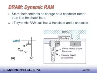
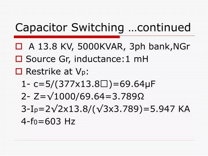
Capacitor Switching …continued. A 13.8 KV, 5000KVAR, 3ph bank,NGr Source Gr, inductance:1 mH Restrike at V p : 1- c=5/(377x13.8)=69.64 μ F 2- Z=√1000/69.64=3.789 Ω 3-I p =2√2x13.8/(√3x3.789)=5.947 KA 4-f 0 =603 Hz. Subsequent Occurences. C.B. Interr. H.F. current at its zero:

E N D
Capacitor Switching …continued • A 13.8 KV, 5000KVAR, 3ph bank,NGr • Source Gr, inductance:1 mH • Restrike at Vp: 1- c=5/(377x13.8)=69.64μF 2- Z=√1000/69.64=3.789Ω 3-Ip=2√2x13.8/(√3x3.789)=5.947 KA 4-f0=603 Hz
Subsequent Occurences • C.B. Interr. H.F. current at its zero: 3Vp on Cap.&at most 4Vp across C.B. • If 2nd B.D. occur, 2nd Osc. I doubles, Vc from +3Vp to -5Vp: If C.B. opens, at most 8Vp across C.B. • further ESCALATION possible • Rs: seq.Restrikes, Cs: subseq.Clearing • Variation of VCB shown in FIG
Other Restriking Phenomena • Seq. restrik. & clearing of C.B. O.V.s (even inductive load) • low p.f. results in Vp at zero current • Dominant fTRV=ω0/2Π= 1/[2Π√L2C] ;Fig. • Several KHz if C stray Cap. small • reigniting effect; heuristic approach: • Superposition of :Vs(0) effect + Vc(0) effect • I=Vm/[ω(L1+L2)] sinωt • I1(0)+I2(0)=I(0)≈I’t(during short duration) • I’= Vm/[L1+L2]
Restriking cct: reignition after isolating inductive load • Equivalent CCT • Short interval ∆t0 • source sub. Battery • I1&I2 rising ramp as current restab. • Ramp component1: Vs(0).t/[L1+L2] • f01=1/2Π x {√[L1+L2]/L1L2C}
Discussion Continued …. Now superposing effect of the Capacitance Initial Voltage Vc(0) at reignition: Surge impedance: Z0=√{L1L2/[c(L1+L2)]} • The Osc_component2: Ic=Vc(0)/√{L1L2/[c(L1+L2)]} • fraction L1/(L1+L2) of it pass L2 • fraction L2/(L2+L2)of it pass L1
Formal Solution • Two Loops Equation: L1 dI1/dt+Vc(0)+1/c∫(I1-I2)dt=Vs(0), (1) Differ.(1): dI1/dt+I1/L1C-I2/L1C=0, (2) Vc(0)+1/C∫(I1-I2)dt=L2 dI2/dt, (3) • L.T. of Eqs (2) & (3) respectively: (s+ω1)i1(s)-ω1 i2(s)=s I1(0)+I1’(0) (4) ω2i1(s)-(s+ω2)i2(s)=sI2(0)+I’2(0) (5) • I’1(0)=Vs(0)-Vc(0)/L1, I’2(0)=Vc(0)/L2 • ω1=1/L1C, ω2=1/L2C
Discussion of Formal Solution • Solving Eqs (4) & (5) simultaneously • yields current 2 comp.s: 1- a ramp component 2- a damped oscillating component with: √(ω1+ω2) =√[(L1+L2)/L1L2C] • In first method assumed I2(0)=0 true if Reignite at peak of TRV • sys Gr Neutral, this fault High Cur.& cause Damage • All sys Gr directly or through some stray C • So: “ARCING Gr” Next Discussion
ARCING GROUND • L-Gr fault:arc;ph & Gr stop&Reig.repeated • Fig of simple model without sources • C1 :ph to ph cap. • C0 :ph to Gr cap. • N at Gr potenial • A to Gr shift V; Ep=1pu • VA neg.peak at F. instant • Shift shown in phasor D.
Discussion of Arcing Gr. results • C0 of A discharge;N rise to Ep & B,C rise • C1&C0 share charges at B and C not at once to Diagram values • Charge Conservation: V(C0+C1)=1/2C0Ep+3/2C1Ep • V=Ep/2[(C0+3C1)/(C0+C1)] • VB&VC rise to 3/2Ep osc. C0,C1&Ls CCT shown in Fig.
Discussion Continued … • Equivalent CCT • f0=1/{2Π√3L(c0+C1)} • Z0=√{3L/4(C0+C1)} • VB&VC above 3/2 Ep • Ip=(3/2Ep-V)/Z0 • subs. for V&Z0: Ip=2Ep(C0/C0+C1)x √{(C0+C1)/3L} □ IB pass out of node Bdivided:Ic1,Ic0 □ Ic1 pass the arc; its frac.: C0/(C0+C1) □Also a 60Hz current due to VA throughCN
What Happens Afterward? • Depends on Arc behavior: 1-Iarc till next p.f. zero in 1/2cycle 2-Iarc immed. Ceased in 1st zero of the IHF • If 1, occur : after ½ cycle; since A is still at Gr level;N in -1pu • 3ph Phasors in next Fig a • N keeps -1pu and after 1/2cycle: VA rise to -2pu Fig b
Phasor Diagram after interrupting a reignition current • Fig a & b • If Reignite again : similar shift ∆V=2pu Rather than 1pu • Transients higher • N -1pu 1pu • Swings of A & B • Then seq. can repeat
continued on case 1& then Case2… • after 1/2cycle A,Gr however at +peak • B&C instant. -1.5pu to Gr • If now arc interrupts VN change -1pu • After ½ cycle exactly as last fig b • Case 2 : If interrupt at 1st zero of IHF occur at point P of curves 1-Vc1,Vc2attain Vp 2-Arc extinguish C1 s rise to VLL(VAC=VAB=1.5pu) • Vp=1.5Ep+(1.5Ep-V)=3Ep-V
Continued on Case 2 i.e. Vp-3/2Ep=3/2Ep-V across arc path □ N has corresponding Disp. □Phasor Diag.Fig.a □different from 1st fig □Then arc interruption at p.f. current zero when Vmax=VAG, 1/2cycle later, situation of figb
Discussion • transient following next reignit. Is greater • Arc is interrupted in 1st H.F. zero I • neutral displacement increases • increase in energy trapped on zero seq Cap escalate the voltage • How to suppress arcing Gr OVs: 1- an appropriate reactance in neutral 2- Peterson coil , sensitive for fault detection
Assignment No. 3 • Ques. 1: • C1=2μF,C2=.38μF • L=800μH,R=5Ω • VC1(0)=75 KV • S closes, compute 1-Max energy in L? 2-t0 instant current flow in c2 3-Vc1(t0)? 4-Max of Vc2 ?
Solution of Question 1 • Z0=√L/C1= √800/2=20Ω • S close: Ipeak(undamped)=75/20=3.75KA • λ=Z0/R=4(fig 4.4) Ip=0.83x3.75= 3.112 KA • Emax=0.0008x3.112^2/2=4.12KJ • I flows in C2 when reversesfig4.4 at t’=3.15 • or t=3.15√LC1=126μs, (T=40μs) fig4.6 Vc1=-0.69x75=-51.75 KV
Eq. CCT (Diode goes off) • series RLC CCT • At this instant: Vc1(0),Vc2(0) required • CCT diff. Eqs employed • Solved for Vc2
Solution of Question 1 continued • 2nd1/2cycle,Vc1(0)=51.75KV,Vc2(0)=0,I(0)=0 • C1&C2 now in series Ceq=C1C2/(C1+C2) • Z0’=√(800x2.38)/(2x0.38)=50.05Ωλ’=50/5=10 • Now for series C1,C2,R,L we have: Vc1+Vc2=RI+L dI/dt (1) I=-C1 dVc1/dt=-C2 dVc2/dt (2) Vc1=Vc1(0)-1/C1∫Idt=Vc1(0)+C2/C1Vc2 (3) Solving Eqs 1,2,3 for Vc2: dVc2/dt+R/LdVc2/dt+{(C1+C2)/LC1C2}Vc2= -Vc1(0)/LC2 svc2(s)-sR/LVc2(0)-R/LV’c2(0)+sR/Lvc2(s)-√{(c1+C2)/LC1C2}xVc2(s)=-Vc1(0)/sLC2
Solution of Q1: ..continued • I(0)=0V’c2(0)=0,T=√{Lc1c2/(c1+c2) • vc2(s)= -Vc1(0)/LC2 x 1/{s(s^2+Rs/L+1/LC)} where C=C1C2/(C1+C2) λ’=10fig4.7 : Vpeak=1.855 1pu=-T^2.Vc1(0)/LC2= =-C1/(C1+C2)Vc1(0)=-2/2.38 x (-51.7)=43.48KV Vpeak=1.855x43.48=80.7 KV
Question 2 , C.B. opening resistor • C.B. clear 28000 A sym fault • R=800Ω, Cbus=0.04μF, • Vsys=138KV,f=50Hz • 1-Peak of TRV? • 2-energy loss in R (it is 2 cycle in)?
Q2, Solution • X=138/(√3x28)=2.8455, L=9.1 mH • Without R, TRV=2x138x√(2/3) =225.4KV • Z0=√L/C=√{0.0091/0.04x10^-6}=477Ω, η=800/477=1.677 • fig4.7 1.38x 225.4/2=155.5 KV • Energy dissipated in 2 cycles: VTRV=112.7{1-exp(-t’/2η)x sin.. +cos…} Integrating Ploss=VTRV/R over ωt=0 to ωt=4Π for a (1-cosine) wave:(1-cosx)=1+cosx-2cosx
Q2 continued • ∫(1-cosωt) dt= 3/2t+1/(4ω) sin2ωt-2/ω sinωt=6Π/ω t=0,4Π/ω • Energy loss if TRV was a 1-cosine wave: V/Rx6Π/ω=112.7/800x6Π/314=0.9526MJ (952.6KJs) • However (1-cosine) is deformed and assuming to be halved : Energy loss≈952/2=476 KJs
Question 3 • 246 KW Load on a 3ph S.G., 13.8 KV p.f.=0.6 lag(load parallel RL) Cpf=1 load+cap switch as a unit • S opened, Vpeak across C.B.? • Zs negligible
Q3, solution • V/R=246 KW, R=(13.8/√3)/246/3=774Ω • p.f.=0.6, Φ=53.13 • tanΦ=1.333=R/X X=580.6Ω,L=1.84 H Xc=580.6 • C=1/(314.15x580.6)=5.48μF • switch open at Is=0, Vs=0, when IL&IC are at peak (opposite sign) • Ipeak=13.8√(2/3) /580.6=19.41 A
Q3, solution continued … • CCT a parallel RLC • -cdVc/dt=Vc/R+ 1/L∫Vcdt+IL(0) • dVc/dt+1/RCdVc/dt + 1/LC =0 • [s+s/RC+1/LC]vc(s)=(s+1/RC)Vc(0)+V’c(0)
Q3 continued • V’c(0)=-Vc(0)/RC-IL(0)/C, Vc(0)=0 • vc(s)=-IL(0)/{c[s^2+s/RC+1/LC]} • without R -IL(0)/c x 1/(s^2+ω0^2) • and : Vc(t)=-IL(0)/Cω0 sinω0t =-IL(0) √L/C sinω0t • √L/C=√1.84/5.48=579.5Ω, • IL(0)=19.41 A Vpeak=11.27KV • η=R/Z0=1.333 fig 4.4 0.6x11.27=6.76KV
Transformer Magnetizing current • Mag. Inrush transient • Im=0.5 to 2% rated, non-sinusoidal • Distortion ~ B in core • Instant of energizing & Residual Flux can cause Inrush • Continue several sec, small Transf. several min, large Transf. • 1000KVA, 13.8KV: load 42 A, Inrush peak 150 A • A DC declines and finaly mag. current
Ferroresonance • series Resonance Very H.V. across C&L (series LC) if excited ~ Natural Freq.
Example of Transformer Ferroresonance • simulate nonlinearity of core: L=dΦ/dt=A exp(-I/B):I=0, L=A; I=B, L=A/e • A 13.8 KV step down T. resonance with cables in primary CCT, A=8H,B=1.76 or L=dΦ/dt=8exp(-I/1.76) • if 60Hz res. Occur in L=4H, C=1/ωL=1.75μF • neglecting resistance: L dI/dt+1/C∫I dt=V sin(ωt+Φ) 8 exp(I/1.76) dI/dt + 10^6/1.75∫I dt=13.8√2/3 sin(377t+Φ) • A nonlinear Diff. Eq. solved for I and then V, Φ=0,45