Download
1 / 17
170 likes | 265 Vues
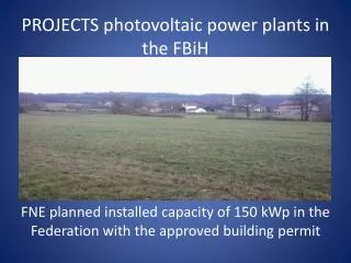
Diagnostics of photovoltaic power plants operation. V i t e zslav Benda , CTU Prague, Faculty of Electrical Engineering. Progress in photovoltaics. Czech Republic. Installed power of PV plants in Czech Republic 2006 0,4 MW p 2007 4,7 MW p 2008 5 8 MW p

E N D
Diagnostics of photovoltaic power plants operation Vitezslav Benda, CTU Prague, Faculty of Electrical Engineering
Czech Republic Installed power of PV plants in Czech Republic 2006 0,4 MWp 2007 4,7 MWp 2008 58 MWp 2009 485 MWp 2010 1958 MWp A proper function of built PV power stations is very important
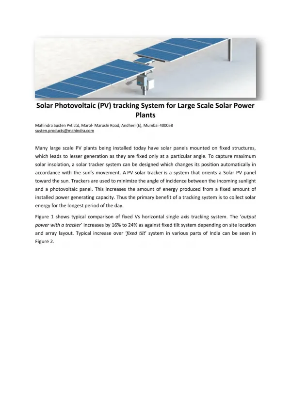
PV Systems Configurations • Central inverters • 10 kW-250kW, three-phase, several strings in parallel • High efficiency, low cost, low reliability, not optimal MPPT • Used for power plants • Module inverters • 50-180W, each panel has its own inverter enabling optimal MPPT • Lower efficiency, difficult maintenance • Highercost/kWp • String (Multi)inverters • 1.5-5 kW, typical residential application • Each string has its own inverter enabling better MPPT • The strings can have different orientations • Three-phase inverters for power < 5kW
Technical Description of a photovoltaic power plant • PV modules • supporting structure • inverter(s) • central • decentral • switchboards • transformer for a conversion to a high voltage output
Tens of millions of PV modules installed http://www.azsolarcenter.com IEA-PVPS* http://www.solaroregon.org IEA-PVPS* http://www.lauritzen.biz IEA-PVPS* IEA-PVPS*
35 MWp power station in Veprek (20 km from Prague) • 186 960 panels rated at 185Wp and 190Wp each (Phonosolar) • 3300 SMA 10 kW and 11 kW inverters using a (multi)string configuration • 26 transformers from 0.4kV to 22kV • 1 transformer connects the total generated power to the 110 kV high voltage power line
The procedure for detection and removal of operational failures • fault in a PV module • fault in interconnection (connectors/cables/switchboard) • fault in inverter (monitoring system)
A) Data collection system • shows the performance of all inverters • the problem is localized if a power loss appears on one inverter (relative to an average performance of all of the inverters) • Comparison of normalized inverter yields for 23.11.2009 brings following detailed data: • Inverter '2000760653'SN: 2000760653Generator: 11,9 kWpTotal yield: 20,97 kWhSpecific yield: 1,76 kWh/kWpdeviation >8% (8,7%)
The exact localization of a problem could be found under „Plant Logbook“ on „Sunny Portal“ (www.sunnyportal.com)
B) visual checking the corresponding PV string • disconnection of the module, missing or broken module, by obstruction that shades a module, melted or burned junction box, etc. C) checking the switchboard • follows (broken fuses or disconnected breakers, destroyed over voltage protections) D)checkingthe faulty string • should be done and voltage measurement conducted • to localize a faulty connector, it is necessary to measure the modules as pairs
E) check the temperature distribution • under load over the modules can be evaluated using IR camera • ”Hot spot” appears together with the presence of local shading or when a single cell is cracked/damaged Problematic parts of the PV systém can be detected
F) checking the I-V characteristic B) Increased series resistance A) Common I-V curve characteristics D) Interrupted chain of cells or completely shaded cell C) Cracked or partially shaded cell
Changing defect parts In the case of modules may be done more detail analyses Precise I-V characteristic measurements Electroluminisce
Conclusions • During PV power plant operation, faults decreasing the • total power output of the power plant may arise. • It can either be a fault in a PV module, failure in a • connection (connectors/cables/switchboard) or a failure • in an inverter. • The inverters are equipped with a monitoring system that • observes the operating parameters, inputs and output and • is able to identify most of the error states. • The identification and removal of the fault should be • carried out in a shortest possible time in order to • minimize losses in energy production.