Download
1 / 5
60 likes | 194 Vues
Power supply. Pulse generator. GPIB. input. ch1. ch2. GPIB. TEST BOARD. Power. Ctest. Vin. OUT_FPGA_1. GPIB. USB. Computer. Multimeter. GPIB. Power supply : Agilent E3631A (GPIB address: 5) Multimeter : Keithley 2000 with scanner at the rear (GPIB address: 16)

E N D
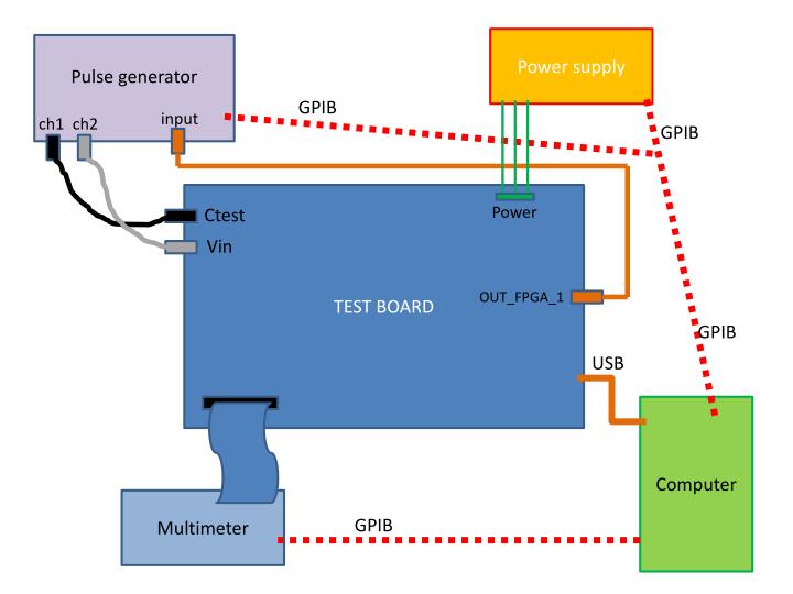
Power supply Pulse generator GPIB input ch1 ch2 GPIB TEST BOARD Power Ctest Vin OUT_FPGA_1 GPIB USB Computer Multimeter GPIB
Power supply: Agilent E3631A (GPIB address: 5) • Multimeter: Keithley 2000 with scanner at the rear (GPIB address: 16) • Pulse generator: Tektronik AFG3102 (GPIB address: 11) • Computer with labview 2010, GPIB board and USB connection • Test board • Packaged ASICs
Automatic tests • Asic consumption: Avdd, Dvdd(with the power supply and GPIB connection) • DC measurements (with the multimeter and its scanner) : • Bandgap voltage: 2.5V • Pedestals : PA (2.5V), FSU (1V), VFS (1V),KI (1.5V) per channels • DAC linearity: DAC PA, DAC FS, DAC KI • Slow control readout: check srout output (just reading our the slow control) • Photon counting tests: Qinj=1/3pe (with the pulse generator) • Scurve versus threshold: trig_pa, trig_fsu • Gain test: scurve versus threshold at different gains (with the pulse generator) • KI tests: (with the pulse generator) • Qinj=2pC/channels, data_ki versus threshold • Threshold defined, data_ki versus input charge for 3 different slow control configurations • All these tests are done automatically. It takes around 6 mn per ASIC.
If the test board is correctly powered and connected this should turn green and usbid = 1 Select the tests you want to perform. By default they will be all selected after configuration. GPIB adresses of the pulse generator and the multimeter The one for the power supply agilent is: GPIB0::5::INSTR Enter the ASIC number and start test when the configuration is done (LED turned to green) Select the different pages to check the results