Download
1 / 15
150 likes | 267 Vues
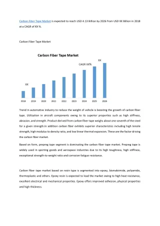
Enrico DA RIVA (EN-CV-PJ) Manuel GOMEZ MARZOA (EN-CV-PJ) 27 th June 2012. Air Cooling by means of carbon fiber structure. Outline. Air cooling: unites cooling performance and material budget. Triangular carbon fiber structure considered, using it for cooling .

E N D
Enrico DA RIVA (EN-CV-PJ) Manuel GOMEZ MARZOA (EN-CV-PJ) 27th June 2012 Air Cooling by means of carbon fiber structure WG4 Meeting - 27th June 2012
Outline • Air cooling: unites cooling performance and material budget. • Triangular carbon fiber structure considered, using it for cooling. • Similar solution as the STARexperiment: 8 m s-1 , 0.1 W cm-2 • Advantages: • Simple cooling system • No extra material added • Disadvantages: • Adequate for low power densities • Restricted air velocity (vibrations) • Sensor temperature uniformity STAR Experiment • Models studied by means of CFD: • Single stave: Thermal fin performance • A two-layer model of the ITS Barrel WG4 Meeting - 27th June 2012
Overview • Single stave: Thermal fin performance • Geometrical features: • CF: 130 µm thick • Si: 50 µm thick • Stave: 300 mm long • Material properties: • CF: k = 620 W m-1 K-1 (assumed to be isotropic) • Si: k = 150 W m-1K-1 • Boundary conditions: • Tair Inlet = 14 °C • vInlet • q’Silicon OUT 268 mm 15 mm IN Si sensor WG4 Meeting - 27th June 2012
Single stave: CFD Analysis 0.3 W cm-2, 10 m s-1 Temperature silicon [°C] Tmax= 60 °C Temperature CF [°C] WG4 Meeting - 27th June 2012
Single stave: CFD Analysis 0.3 W cm-2, 20 m s-1 Temperature sensor [°C] Tmax= 43 °C Temperature stave [°C] WG4 Meeting - 27th June 2012
Single stave: conclusions • Only the case with 0.1 W cm-2 and 10 m s-1 would fulfill the detector thermal requirements for a single stave • The behaviour of the stave as a thermal fin is seen • Thermal performance improved when cooling from both sides of the triangular shape. 0.1 W cm-2, 10 m s-1 Tmax= 30 °C Stave heat flux [W m-2] q’ = 0.3 W cm-2, 10 m s-1 WG4 Meeting - 27th June 2012
Two-layer model: description • 2. A two-layer model of the ITS Barrel: • Only a section including two triangular shapes was modeled • Assumed a 30 mm chamber at the barrel end as recirculation zone • Mesh: ~ 5 million cells • Turbulence model: SST k-ω, Low-Re corrections 30 mm L2 Beam Pipe L1 WG4 Meeting - 27th June 2012
Two-layer model: description • Sector of the ITS barrel was modeled by means of CFD • Two inlet ducts and one outlet per layer • Simplified geometry built from the mechanical CAD design • Total length stave: 300 mm (268 mm sensor) + recirculation region • Material properties: • CF: • T300 fabric (biaxial thermal conductivity) • kPlanar = 400 W m-1K-1 • kTransv= 1.2 W m-1K-1 • Thickness: 130 µm (triangles and separation layers) • Si: k = 150 W m-1K-1 • Boundary conditions: • vInlet = 10 m s-1 • q’Sensor = 0.3 W cm-2 • Tair Inlet = 14 °C WG4 Meeting - 27th June 2012
Two-layer model: CFD study 0.3 W cm-2, 10 m s-1 Magnitude of air velocity in a plane along the volume [m s-1] Pressure drop: L1 = 325 Pa, L2 = 306.28 Pa WG4 Meeting - 27th June 2012
Two-layer model: CFD study 0.3 W cm-2, 10 m s-1 Temperature silicon L1 [°C] Temperature silicon L2 [°C] WG4 Meeting - 27th June 2012
Two-layer model: CFD study 0.3 W cm-2, 10 m s-1 Heat flux silicon in triangle L2 [W/m2] Heat flux to outlet L2 [W/m2] WG4 Meeting - 27th June 2012
Two-layer model: CFD study 0.3 W cm-2, 10 m s-1 Temperature CF stave L1 [°C] WG4 Meeting - 27th June 2012
Outcome • The silicon is only cooled with the air flow inside the triangular duct, because voutlet duct is small. • Possible solutions: • Increase air velocity • Vibration & shear stress increase • Equalize inlet/outlet sections: guarantee high velocity at outlet ducts • Use different cooling fluid • Laminar flow and small molecule: no stresses over mechanical structure • Still, cooling from both sides of the sensor has to be guaranteed AIR HELIUM WG4 Meeting - 27th June 2012
Outcome • The silicon is only cooled with the air flow inside the triangular duct, because voutlet duct is small. • Possible solutions: • Increase air velocity • Vibration & shear stress increase • Equalize inlet/outlet sections: guarantee high velocity at outlet ducts • Use different cooling fluid • Laminar flow and small molecule: no stresses over mechanical structure • Still, cooling from both sides of the sensor has to be guaranteed • Solution to be used for low q’ AIR HELIUM WG4 Meeting - 27th June 2012
Enrico DA RIVA (EN-CV-PJ) Manuel GOMEZ MARZOA (EN-CV-PJ) 27th June 2012 Air Cooling by means of carbon fiber structure WG4 Meeting - 27th June 2012