Download
1 / 12
140 likes | 689 Vues
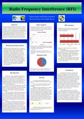
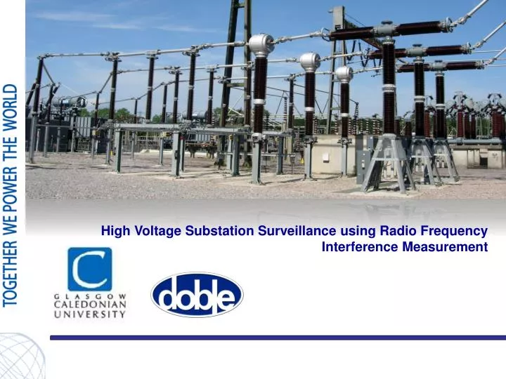
High Voltage Substation Surveillance using Radio Frequency Interference Measurement. Detecting partial discharge (indirect measurement). RFI. Electric. Thermal. Partial discharge. Pressure/ Acoustic. Light. Acoustic . Chemical . RF pulse from a PD related source.

E N D
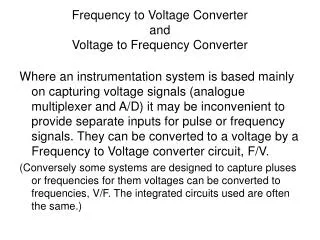
High Voltage Substation Surveillance using Radio Frequency Interference Measurement
Detecting partial discharge (indirect measurement) RFI Electric Thermal Partial discharge Pressure/ Acoustic Light Acoustic Chemical
RF pulse from a PD related source Partial discharge pulse RFI emission FFT frequency spectrum of PD pulse
CASE Inkoo 110 kV CT 5 Selective testing targeting mainly old 110 kV CTs discovered a unit with a high C2 power factor ~0,95 %. (Strömberg KOTU F41 type, manuf. 1972) A DGA follow up showed considerable gassing TCG 18 000 ppm (H2 12037 ppm, CH4 4839 ppm, C2H6 1058 ppm) diagnosed as D1 low energy discharge Suitable test case...? Doble were asked for a PDS100 blind test.
6 Pvm Esityksen nimi / Tekijä
Baseline measurement 7 Baseline measured outside the fences Low backround noise levels Discharges in oil will have higher frequency content GSM Typical frequency zone for air discharges <150 MHz
8 No signals Baseline Suspected item Measuring points on the service road between CBs and CTs
Measurements 9 The faulty unit was succesfully located • A small PD signal was registered ~15dB above baseline • Attennuation of high frequencies is useful in the location process • The 110 kV CT was replaced - no signal after replacement (one month later)
HV Lab testing of the CT 10 • PD Ignites at 74 kV phase-to-earth voltage (128 kV main voltage), apparent charge was 50-60 pC • Extinguishing voltage is considerably lower around 45 kV (77 kV main voltage) • At 1,2 x Um/ (85 kV) discharge level was 150 pC • Internal pressure 0,75 bar (0,6 considered normal) • Tandelta slightly increasing as a function of voltage up to 70 kV, 0,43...0,59 % • Tandelta increases rapidly when PD ignites at 74 kV being 1,76 % at 123 kV • CT passed the 0,75 x 230 kV, 50 Hz 1 min overvoltage test
Advantages of RFI Non-invasive, no need for physical or electrical connection. Does not require equipment under test to be taken out of service. May be adopted for first-line substation surveillance. Rate and severity of discharge can be monitored and trended.
Thanks for your kind attention! Questions? Contact: Alan Nesbitt Brian Stewart Glasgow Caledonian University Scotland, UK ane2@gcal.ac.uk Contact: Micael Hellquist Hans Ove Kristiansen Doble TransiNor AS Norway info@doble.no