Download
1 / 20
200 likes | 322 Vues
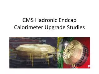
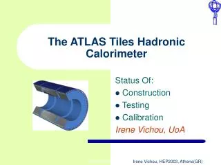
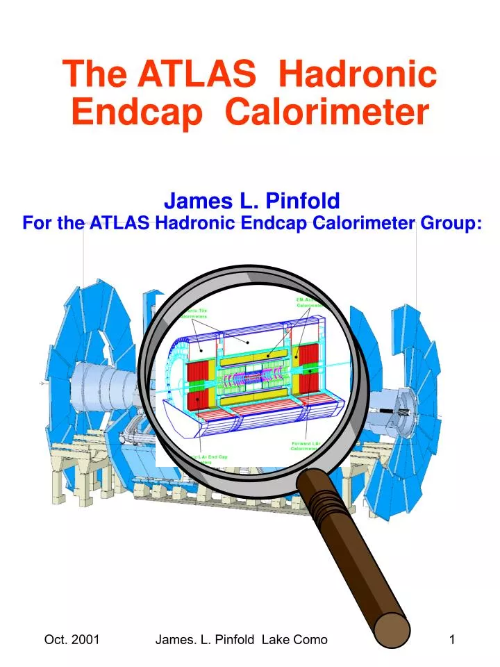
The ATLAS Hadronic Endcap Calorimeter. James L. Pinfold For the ATLAS Hadronic Endcap Calorimeter Group:. Hadronic Endcap Calorimeter LAr-Cu sampling calorimeter covering 1.5 < h < 3.2. GOOD HE JET RESOLUTION (10 l of active cover.)

E N D
The ATLAS Hadronic Endcap Calorimeter James L. Pinfold For the ATLAS Hadronic Endcap Calorimeter Group: James. L. Pinfold Lake Como
Hadronic Endcap CalorimeterLAr-Cu sampling calorimeter covering 1.5 < h < 3.2 • GOOD HE JET RESOLUTION (10 l of active cover.) • FULL HEC+FCAL h COVER (1-5-> 4.8) for good Etmiss determination. • PUNCHTHROUGH TO m –SYSTEM REDUCED by 11l thickness of HEC+support. James. L. Pinfold Lake Como
Hadronic Endcap Calorimeter Construction: Responsibilities • Absorber plate production: • Alberta • Dubna • Protvino • Readout foils: • Mainz • TRIUMF • EST boards • Lebedev • Module stacking centres: • Dubna • MPI Munich • TRIUMF • Protvino • Cold electronics (preamps) + cabling harness: • MPI Munich • Calibration system: • KOSICE • Mainz James. L. Pinfold Lake Como
Hadronic Endcap Segmentation Front mod. 25 plates, rear mod. 17 plates • Composed of two wheels per end, 32 modules per wheel • Front wheel 67 tonnes 25 mm Cu plates • Rear wheel 90 tonnes 50 mm Cu plates • Channel count for both endcaps, 4416 James. L. Pinfold Lake Como
HEC MODULE PAD boards EST boards Honeycomb Copper plates Tie Rods Connecting Bars Cold Electronics James. L. Pinfold Lake Como
HEC Readout • Electrostatic Trans- former readout • Distance between Cu plates 8.5 mm • LAr gaps 1.954 mm • Robust against HV shorts James. L. Pinfold Lake Como
Cu Absorber Plate Production • Three sites Alberta, Dubna, Protvino • Roughly one sector(1/32nd) per month can be machined at Dubna & Protvino. Since June 1st 1999 2->3 per month can be machined at Alberta • Estimate machining finished by early 2002. • Eg Cu machining @ Alberta, using the CSR advanced machining facility: See the machining in realtime moving images http://129.128.162.80/webcam/JavaCam.html James. L. Pinfold Lake Como
Series Production of Modules • 1st module completed in Munich on 4/16/ 99. Module under HV test at TRIUMF James. L. Pinfold Lake Como
Quality Control • Quality control procedures defined in October 1997, updated in November 1998. • 2000 testbeam QC database started at CERN • 2001-> merging of QC databases from CERN +institutes into LAr QC database. Go-NoGo jigs Cu density check Template check James. L. Pinfold Lake Como
Cold Electronics 3 PSBs on back of each front module 2 PSBs on the back of each rear module James. L. Pinfold Lake Como
(7 out of 8 modules will be cold tested) Cold Testing 4 modules in cold test cryostat Modules prepared for a cold test James. L. Pinfold Lake Como
Test Beam Setup (1 in 8 modules will be beam tested) Rotating to vertical Mating the modules Modules in the cryostat James. L. Pinfold Lake Como
Stacking & Insertion of HEC wheels into the Cryostat Stacking Crane Wheel Rotator Air Pads T6 Cryostat James. L. Pinfold Lake Como
Recent & Future Testbeam Test-beam summer 2000 involving 6 series modules in the H6 beamline. Analysis of results recently accepted by NIM Summer 2001– 2 successful test-beam periods . H6 Joint EMEC-HEC test planned for the August of 2002. Using H1 cryostat deploy: 1) EMEC; 2) HEC FRONT; 3) HEC REAR (HALF DEPTH) James. L. Pinfold Lake Como
Test Beam Results (1)Energy resolution for electrons • Reported here are key results from the test of 6 series production HEC modules • Results obtained in the summer of 2000 James. L. Pinfold Lake Como
Test Beam Results (2) • Spatial uniformity of response to electrons as a variation of EM calib. Const. variation Non-uniformity < 1% James. L. Pinfold Lake Como
Test Beam Results (3)Energy resolution for pions James. L. Pinfold Lake Como
Testbeam Results(4)Muon Detection • Using 150 GeV muons (most prob. muon signal James. L. Pinfold Lake Como
Testbeam Results(5) e/h Ratio Ratio of response to electrons and hadrons CMC is an energy dep. leakage correction James. L. Pinfold Lake Como
Final Remarks • Series production well underway 57% (76/134) modules stacked – on schedule • 42% (57/134) modules Cold Tested. • All HEC only beam tests finished this summer! • Joint EMEC-HEC test beam next summer. • Joint EMEC-HEC-FCAL test in 2003 • Stand/Table/Rotator for installation ordered and due December 2001. • Assembly area and clean rooms in Bat.180 ready. • Assembly of the HEC will start in March 2003 in Bat. 180 at CERN. James. L. Pinfold Lake Como