Download
1 / 55
550 likes | 553 Vues
Learn the step-by-step procedure to prepare the Main Injector for access in a faster and more efficient way. Follow the instructions and use the provided tools to ensure a smooth and safe access process.

E N D
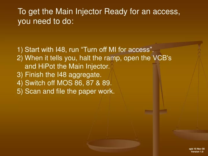
To get the Main Injector Ready for an access, you need to do: • Start with I48, run “Turn off MI for access”. • When it tells you, halt the ramp, open the VCB's • and HiPot the Main Injector. • 3) Finish the I48 aggregate. • 4) Switch off MOS 86, 87 & 89. • 5) Scan and file the paper work. spb 10 Nov 08 Version 1.0
Here’s the aggregate, so why run it?
The purpose of the aggregate, “Turn off MI for access”, is to prepare the Main Injector for an access in a faster and more efficient way than doing it by hand or using a check list. Now on to the aggregate…….
Take the Master switch, the next step is to put the Booster in dump mode.
We can watch V803 change polarities, go to Positive Mode.
The aggregate will put the Booster into Dump Mode. Turn off: B:MH1, B:LAM, B:CRDEV, B:BS809. And set B:V803 to Positive Polarity. Waits 30 seconds and checks if B:V803 is in Positive Polarity and B:BS809 is off. Now to turn Booster on in dump mode. Reset B:CRDEV and turn on the Master Switch.
Now we turn off beam lines that will be affected by turning off the Main Injector. With the Booster in Dump Mode, no beam from Linac or Booster can get into the Main Injector. P150 and A150 lines, prevent beam getting to the Main Injector from the Tevatron: I:LAM52, I:V701, I:P1CRD I:LAM62, I:V901, I:A1CRD No beam can get into the Main Injector, now to turn off areas that require the Main Injector as an input to their CDC. Recycler: R:VDPA1, R:VDPA2 and R:CRDEV Tevatron: T:LAM, T:TEVCRD NuMI: I:LAM60, I:LAM61, E:HV101, E:NUMCRD Pbar Accumulator and Debuncher: D:H704, D:BSC700, D:AP0CD2 D:H926, D:BSC925
We have turned off the CDC’s and major supplies, now onto the smaller ones, which will be done by using files to turn them off and to check if they were turned off.
File #40 will turn off the NuMI supplies which are powered by MOS 89.
Next we need to open the VCB’s and HiPot the Main Injector, usually “Bus Only” going into an access and “Bus and PS” coming out. So let’s HiPot the Main Injector.
Next on I17 you will need both the “PS Status & Control” and “PS & HiPot Loop Control” windows.
With the VCB's opened, drop the permit by clicking on “Test Reset”.
Select “Bus & PS HiPot” or “Bus Only HiPot”. Normally you would choose “Bus Only” when turning off and “Bus & PS” when turning on. Click on the selection you want to HiPot.
Select a combination of “QF”, “QD” and “Bend” from the “HiPot Loop Controls”.
The HiPotter Window” Choose Quads, Bends or all to plot. Click to start the plot, it’s a live active plot. Good only when current is on. Click here to get the analysis, after you did the HiPot.
Now you are ready to unlock the HiPot power supply, unless someone has done it for you.
Unlock and switch on the disconnect,following the NFPA 70E procedure.
Turn on the Power Supply 1. Verify the Kilovolt knob is set to 0. 2. Turn on the Power Supply On/Off Switch. 3. Next, press the High Voltage Button. 4. Knob to run up the Volts, keeping an eye on the Current.
Chassis is on and ready to run up to 1KV. Note: The polarity should be “negative”, if not, contact an Expert And the HV is on. The power is on.
Run up to 1kv The current At 1kv Knob to run up the Voltage.
Now with the High Voltage at 1KV, you can go back to the I17 program.You have the plot running, which will tell you the current. Now click on “Perform HiPot Analysis“. Put both plots in the Main Injector Logbook and the record the current in the OPS Logbook.
Here are the HiPot plot and HiPot Analysis graphics. Put both in the Main Injector Elog and record the current in the OPS Elog.
Run down the voltage. Knob to run down the Voltage.
Turn off the Power supply switch. Power Supply On/Off Switch
Put the HiPot key back in the Main Injector lockout box. It’s back.
The Main Injector has been HiPotted and the HiPot power supply is locked off, now finish the aggregate.
The next command “ACL MITRNOFF” script will launch on your SA, a graphic showing the status of the power supplies that will need to be turned off, see next slide.
Here we can watch and verify that these power supplies are turned off.
Next the aggregate bypasses the “MI ACCS” list for the Main Injector alarms.
Comment Interact asks you to enter your initials, so it can log who ran the aggregate.