Download
1 / 22
300 likes | 498 Vues
EE4220 Communications system. Introduction to Digital Subscriber Line (DSL). Dr. Hassan Yousif Electrical Engineering Department College of Engineering Salman Bin Abdulaziz University. Lect no-4. Definitions of Broadband.

E N D
EE4220 Communications system Introduction to Digital Subscriber Line (DSL) Dr. Hassan Yousif Electrical Engineering Department College of Engineering Salman Bin Abdulaziz University Lect no-4
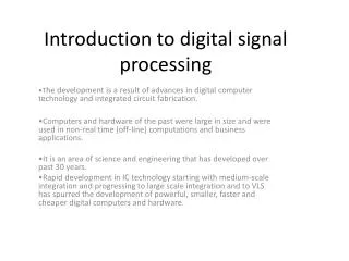
Definitions of Broadband • In telecommunications, broadband is wide bandwidth data transmission with an ability to simultaneously transport multiple signals and traffic types. • The medium can be coaxial cable, optical fiber, twisted pair, DSL local telephone networks or wireless broadband. • In contrast, baseband describes a communication system in which information is transported across a single channel. • Broadband refers to a communication bandwidth of at least 256 kbit/s. Each channel is 4 MHz wide, and it uses an extensive range of frequencies to effortlessly relay and receive data between networks
In telecommunications, a broadband signaling method is one that handles a wide band of frequencies. Broadband is a relative term, understood according to its context. The wider (or broader) the bandwidth of a channel, the greater the information-carrying capacity, given the same channel quality. • In radio, for example, a very narrow band will carry Morse code, a broader band will carry speech, and a still broader band will carry music without losing the high audio frequencies required for realistic sound reproduction. • A television antenna may be described as "broadband" because it is capable of receiving a wide range of channels, while a single-frequency or Lo-VHF antenna is "narrowband" since it receives only 1 to 5 channels.
In data communications a 56k modem will transmit a data rate of 56 kilobits per second (kbit/s) over a 4-kilohertz-wide telephone line (narrowband or voice band). The various forms of digital subscriber line (DSL) services are broadband in the sense that digital information is sent over multiple channels. Each channel is at higher frequency than the baseband voice channel, so it can support plain old telephone service on a single pair of wires at the same time. • However, when that same line is converted to a non-loaded twisted-pair wire (no telephone filters), it becomes hundreds of kilohertz wide (broadband) and can carry up to 60 megabits per second using very-high-bitrate digital subscriber line (VDSL or VHDSL) techniques.
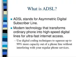
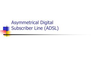
Digital subscriber line (DSL; originally digital subscriber loop) is a family of technologies that provide internet access by transmitting digital data using a local telephone network which uses the Public switched telephone network. • In telecommunications marketing, the term DSL is widely understood to mean asymmetric digital subscriber line (ADSL), the most commonly installed DSL technology. DSL service is delivered simultaneously with wired telephone service on the same telephone line. This is possible because DSL uses higher frequency bands for data. On the customer premises, a DSL filter on each non-DSL outlet blocks any high frequency interference, to enable simultaneous use of the voice and DSL services.
Digital Subscriber Lines NID – Network Interface Device. DSLAM – Digital Subscriber Line Access Multiplexer. EETS 7304
Introduction Internet Digital Subscriber Line (DSL) Broadband Access DSLAM downstream Central Office DSL modem DSL modem upstream VoiceSwitch LPF LPF Customer Premises Telephone Network DSLAM - Digital Subscriber Line Access Multiplexer LPF – Low Pass Filter (passes voiceband frequencies)
ADSL and Cable Modems • Need for high-speed (broadband) data access • Voiceband data modems can yield 53 kbps (kilobits per second) • Telephone voice channel capacity ois 64 kbps (the Central Office samples voice signals at 8 kHz using 8 bits/sample) • Integrated Services Digital Network (ISDN) modems deliver 128 kbps • New modem standards are necessary to meet the demand for higher bandwidth access for telecommuting, videoconferencing, video-on-demand, Internet service providers, Internet access, etc. • Two standards tested in 1998 and now widely available • Cable modems • Asymmetric Digital Subscriber Line (ADSL) modems • Cable Modems • Always connected to the Internet • Your neighbors on the same local area network share the bit rate • Local area network provides either 27 or 36 Mbps downstream, and between 320 kbps and 10 Mbps upstream.
ADSL Modems • ADSL modems • Always connected to the Internet • Call central office using a dedicated telephone line which also supports a conventional Plain Old Telephone Service (POTS) line for voice • Connection time is 5-10 seconds • ADSL modems are capable of delivering 1-10 Mbps from the central office to the customer (downstream) and 0.5-1 Mbps from the customer to the central office (upstream) • Although ADSL lines have been available from Southwestern Bell since the Fall of 1997, ADSL modems were not commercially available until Fall of 1999.
Asymmetric digital subscriber lines (ADSL) • Asymmetric digital subscriber lines (ADSL) transmit high • bit rate data in the forward direction to the subscriber, and lower bit rate data in the reverse direction to the central office, both on a single copper telephone loop. • The European Telecommunications Standards Institute (ETSI) and the American National Standards Institute (ANSI) have defined standards for ADSL transceivers. • Both of these standards propose the use of discrete multi-tone (DMT) as the modulation technique for ADSL transceivers. DMT divides the effectively band-limited communication channel into a larger number of orthogonal narrowband subchannels.
ADSL transmits data over frequencies up to 1.1 MHz. The limit of 1.1 MHz is due to power constraints imposed by the Federal Communications Commission (FCC). The 1.1 MHz bandwidth is divided into 256 narrowband subchannels downstream (from the service provider to the customer) and 32 subchannels upstream (from the customer to the service provider). Each 4.3 kHz narrowband subchannel has a separate carrier, and the carriers are harmonically related. This type of data transmission is known as DMT modulation, which is the type of multicarrier modulation proposed in the ADSL technical specification. The first channel in ADSL (0-4.3 kHz) is always dedicated for voice. The rest of the channels are specified differently according to two different methods: 1) Frequency Division Multiplexing, where upstream and downstream channels use different frequencies, and 2) Echo Cancellation, where upstream and downstream channels overlaped.
Discrete Multi-tone Modulation (DTM) • The fundamental goal of multicarrier modulation techniques is to partition a data transmission channel with ISI into a set of orthogonal, memoryless subchannels, each with its own “carrier” . Data is transmitted through each subchannel independently of other subchannels. • DMT modulation and demodulation is implemented using the Inverse Discrete Fourier Transform (IDFT) and Discrete Fourier Transform (DFT). To implement an N/2 subchannel DMT system, an N size IDFT/DFT is required. The size is doubled by mirroring the data to impose conjugate symmetry in the frequency domain, which results in real-valued signal in the time domain after applying the IDFT.
Transmitter part job • In the ADSL transmitter shown in above Fig, an input bit stream is first partitioned into substreams using a serial-to-parallel (S/P) converter. Each substream is then encoded using quadrature amplitude modulation (QAM), which produces a complex number representing each encoded bit substream. • The outputs of the QAM encoder are mirrored and conjugated before they enter an N point IFFT, where N/2 is the number of subchannels. The mirroring creates real values at the • output of the IFFT.
Receiver part job • An ADSL receiver receives the data through the channel, which is modeled as an FIR filter. The operation of the receiver is the dual of that of the transmitter, plus the addition of an equalizer. • The equalizer has two tasks: • 1) reduce ISI in the time domain and shorten the channel impulse response to the CP limit, • 2) compensate for magnitude and phase distortion in the frequency domain
Transmitted Signal Power Received Signal Power Signal to Noise Ratio (SNR) Received Noise Power Signal Attenuation SNR is responsible for the performance 64 kHz MHz Frequency