Download
1 / 21
300 likes | 840 Vues
GPS and other GNSS signals. GPS signals and receiver technology MM10 Darius Plausinaitis dpl@gps.aau.dk. GPS Signals MM10-MM15. MM10 | GPS and other GNSS signals MM11 | GPS signals - Code Generation and Carrier Generation MM12 | GPS signals - Acquisition of the GPS Signal

E N D
GPS and other GNSS signals GPS signals and receiver technology MM10 Darius Plausinaitis dpl@gps.aau.dk
GPS Signals MM10-MM15 • MM10 | GPS and other GNSS signals • MM11 | GPS signals - Code Generation and Carrier Generation • MM12 | GPS signals - Acquisition of the GPS Signal • MM13 | GPS signals - Code Tracking and Carrier Tracking • MM14 | GPS signals - Navigation Data Decoding • MM15 | GPS signals - Calculation of Pseudoranges and Positions http://gps.aau.dk/educate/receiverTechnologyPart3.htm
Today's Subjects • GPS Signal • Codes, carriers, navigation data • Signal Bandwidth • Overview of today's and future GNSS signals • Spread Spectrum Technique • PRN Codes • Correlation and other signal properties • GPS Signal Generation
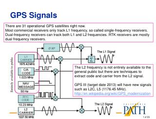
GPS Signals • Transmission frequencies: • L1 = 1575.42 MHz = 154 x 10.23 MHz • L2 = 1227.6 MHz = 120 x 10.23 MHz • (Upgrade) L5 = 1176.45 MHz = 115 x 10.23 MHz (for civil use) • (Upgrade) New military signal (M-code) and a new civil signal (L2CS)
GPS signal • C/A codes • Chipping rate of 1.023 Mcps • Length of 1023 chips • Chip duration ~ 1µs ~ wave length 300 m • Repeats every millisecond • 32 different sequences assigned to GPS satellites • P(Y) codes • Chipping rate of 10.23 Mcps • Length ˜1014 chips • Chip duration ~ 0.1µs ~ wave length 30 m • Repeats every week • Anti-spoofing
GPS Navigation Data • Bit-rate of 50bps • Ephemerides • Satellite clock information • Satellite health and accuracy • Almanac • Repeated every 12.5 minutes • More details in MM14
WAAS and EGNOS • Provide facilities to obtain better position accuracy by: • Correction of ephemeredes errors • Providing more accurate Ionospheric model • GPS C/A type signals (same modulation, frequency and spreading codes) • Much higher data rate (500sps - 250 bps) • Forward Error Correction • Much lower Doppler (<210Hz instead of 5kHz) • EGNOS is designed as a support system for GALILEO
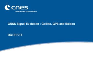
Galileo • More signals transmitted on each frequency (comparing to today’s GPS) • Longer spreading codes • Data less signals • BOC modulation • Forward Error Correction • Block Interleaving (bit scattering) - to make the long data losses manageable. • Uplink emergency signal
GLONASS • Two frequencies • More accurate comparing to GPS in stand alone applications. • Separate carrier frequency per satellite. • 0.511 Mcps civil signal and 5.11 Mcps military spreading codes • 12 satellites operating
GNSS signals – today and future • Relative locations of GNSS signals EGNOS andWAAS are using GPS L1 E5 E6 E2 L1 E1 E5a E5b L5 L2 L2 L1 L1 1610 MHz 1194 MHz GNSS systems: GALILEO GLONASS GPS
DSSS Technique • Used for Code Division Multiple Access (CDMA) systems: • All users transmit on the same frequency • The frequency spectrum of the signal is spread with a noise like code • Spreading codes have very low cross-correlation and are unique for every user • Transmission bandwidth is much higher than information bandwidth (but several users can share the same band) • Resists jamming • Very low interference with other signals because of large bandwidth and low power
Pseudo Random Noise (PRN) • Noise-like properties Very low cross-correlation with other signals • PRN sequences (codes) are almost orthogonal High auto correlation only at 0 lag and very low cross correlation • PRN codes are created by shift registers of length n • Length of PRN sequence is calculated as: NDS= 2n -1
Spreading operation • Data signal is multiplied by a PRN code (XOR operation for binary signals) • The result signal has PRN like properties • An example of a spreading operation and the BPSK modulation: 1 bit period 1 chip period Data bits DSSS code chips Data * DSSS code Carrier Carrier after BPSK
Frequency spectrum plot • Wide band signal is less affected by narrow band interferences • A high power narrow band interferences are spread by the de-spread operation (at the receiver) to low power high bandwidth interference. • Hard to detect DSSS type signal without correct codes • Hard to jam
Encoding / Decoding Narrowband signal Narrowband signal Wideband signal Multiplication- Spreading Multiplication- De-spreading or Correlation PRN code generator PRN code generator
Literature • http://www.navcen.uscg.gov/gps/modernization/ • http://gps.faa.gov/Programs/WAAS/waas.htm • http://www.esa.int/esaNA/galileo.html • http://www.esa.int/esaNA/egnos.html • http://www.glonass-center.ru/ • Read Interface Control Documents for detailed description of the GNSS signals