Download
1 / 30
300 likes | 378 Vues
Computational Modeling in Support of the Magnetic Intervention Concept. D. V. Rose,* T. C. Genoni, R. E. Clark, D. R. Welch, and T. P. Hughes Voss Scientific, LLC

E N D
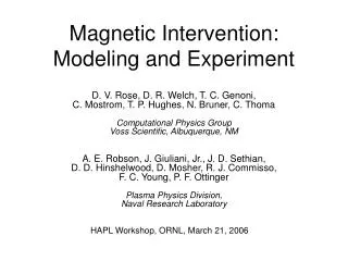
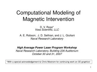
Computational Modeling in Support of the Magnetic Intervention Concept D. V. Rose,* T. C. Genoni, R. E. Clark, D. R. Welch, and T. P. Hughes Voss Scientific, LLC A. E. Robson, J. D. Sethian, and J. Giuliani, Jr.Naval Research LaboratoryHAPL MeetingPrinceton Plasma Physics LaboratoryDecember 12-13, 2006 *David.Rose@vosssci.com
Outline • Description of EMHD model in cylindrical coordinates (based on model of D. Hewett) • Direct comparison of explicit PIC simulation to EMHD model • EMHD model of R. E. Pechacek magnetic intervention experiment • Preliminary EMHD modeling of “chamber-scale” magnetic intervention • Next steps…
1.) EMHD model implementation based on work of D. Hewett* • We have implemented a version of D. Hewett’s 2D cylindrical (r,z) field solver (advancing Aq) • Model includes “correct” evolution of vacuum magnetic fields • Field solver implemented within Lsp code framework *D. W. Hewett, J. Comp. Phys. 38, 378 (1980)
Equation for Aq Conductivity is assumed to be a scalar to avoid carrying extraterms Bq can be obtained between ADI passes, but we have not implemented this yet. In vacuum, this equation reduces to:
Model Constraints: • Most of the computational constraints associated with our previous EMHD solvers also apply here. • In addition, a “grid-Reynolds” constraint applies, that when combined with the usual diffusion-rate constraint give the following inequality:
2.) Comparison of explicit EM PIC simulation and EMHD simulation: • Important benchmark of the EMHD model • Assess impact of EMHD approximations on magnetic intervention modeling • Explicit EM PIC uses • Inertial macro-particles for both ions and electrons • Complete set of Maxwell’s equations on finite grid
The comparison is carried out using the simulation geometry for the (ill-fated) Gamble II experiment*: • Explicit simulations for this problem geometry already completed. • Relatively small-scale simulation problem for the EMHD algorithm (easily satisfying computational constraints for a relatively high conductivity) • PIC simulations demonstrated diamagnetic penetration of a plasma into an applied magnetic field with a well defined electron sheath formed at the plasma/magnetic-field interface *See D. V. Rose, et. al presentation, HAPL Meeting, ORNL, March 21, 2006
Gamble II Experiment: Schematic Single-turn coil 30 cm Gamble II 20 cm C L 70 cm 10-30 cm A portion of the total proton beam enters the chamber through an aperture.
Comparison: Proton dynamics at the sheath are essentially equivalent at 40 ns. EMHD Protons EMHD sim: ~15,600 particles (protons) Explicit PIC sim: ~ 2,000,000 particles (1,700,000 electrons, 300,000 protons) PIC Protons PIC Electrons
The proton density at 40 ns is remarkable similar: the density pile-up at (r,z)=(12,42) is even present, although less well resolved in the EMHD simulation. EMHD proton density PIC proton density
Contours of |B| in the vicinity of the sheath are in agreement. EMHD solution at large radius and on opposite side of coil is bad.
E-fields in vacuum region are huge (up to 10^4 kV/cm) and non-physical in the EMHD calculation by 40 ns. PIC shows E-fields confined to thin sheath region only. PIC EMHD
3: Pechacek Experiment Modeling • A two-stage laser system drives a 1-mm scale, solid D2 pellet forming a plasma. • The plasma is created inside the void of a cusp magnetic field. • The adiabatically expanding plasma compresses the cusp field lines. • Plasma ions escape from the “point” and “ring” cusps in the field geometry. • Plasma ions are “deflected” away from the chamber walls *R. E. Pechacek, et al., Phys. Rev. Lett. 45, 256 (1980).
The grid-Reynolds constraints suggests a reasonably wide parameter space for the Pechacek experiment Simulationparametersused in thispresentation
Magnetic field evolution (|Aq|): 0 1 2 Framesat nms times 3 4 5
Ion Density Evolution: 0 1 2 Framesat nms times 3 4 5
Status: Pechacek Experiment Modeling • Present modeling is providing the best results to date, and detailed comparisons with the data are very compelling. • Some problems resolved others remain with the EMHD solver (more work is required). • Additional developments such as convergence testing and the use of canned, parallelized solvers (e.g. PETSC) are expected to make the algorithm faster.
3. Chamber-Scale Magnetic Intervention Simulation: • A preliminary simulation result using the new solver and 5 species from the Perkins ion spectra is given (H, D, T, 4He, 12C). • For computational expediency, ion distributions all truncated at vi=0.1c. • 4-coil magnetic field topology taken from previous “shell” model calculations of Robson and Genoni.
Computational constraints are significant for these ion speeds and scale lengths: Parameter regimeexplored in this report.
400 ns 0 200 ns 600 ns 1000 ns 800 ns
400 ns 0 200 ns He iondensity 600 ns 1000 ns 800 ns
Ion current densities at point and rings cusps are less than ~1 kA/cm (so far!)
Status: Magnetic Intervention Chamber Modeling • A representative “shell” simulations are consistent with “shell” models of Robson and Genoni. • Problems with the convergence of the solver (as seen in the Pechacek simulations) need to be resolved. • Unlike the Pechacek experiment, the magnetic intervention parameter regime ion speeds and scale lengths may require significant computational resources using the EMHD algorithm. A parallel implementation of this algorithm is essential.
5: Next Steps… • Continue to refine EMHD solver… • Non-uniform grids • Parallel implementation • Complete analysis of Pechacek experiment and document • Continue examination of magnetic intervention physics issues • Shock acceleration of ions at sheath… • Currently revisiting perfectly conducting “shell” model formulation for use on a fixed grid with arbitrary number of particles.
EMHD simulation used ~15,600 particles (protons) Explicit PIC simulation used ~ 2,000,000 particles (1,700,000 electrons, 300,000 protons)
Experimental Parameters • Chamber wall radius is 30 cm (not shown) • External field coils, 67 or 70 cm diam, 70 cm separation. • |B| = 2.0 kG at ring cusp. • 2x10¹⁹ “D2” ions produced from cylindrical target of 1-mm diam., 1-mm length. • Modeling assumes initial plasma is a thermal (51.1 eV), D+ neutral plasma with initial radius of 2 cm.
Plasma/Field boundary along 27 degree radial line from the cusp center (experimental result):
At r=22 cm inside ring cusp, electron density was measured at 5 different times: Simulations results in reasonable agreement with these measurements (at least for first 3 times):
Simulation dynamics are complex, but energy gain in all species (except protons?) is consistent with diffusion of plasma into sheath.