Download
1 / 52
570 likes | 1.17k Vues
ODS steels – part I : manufacture, mechanical properties and oxidation behaviour. Yann de Carlan, Jean Henry, Ana Alamo Arnaud Monnier Raphael Couturier, Emmanuel Rigal Céline Cabet Commissariat à l’Energie Atomique CEA, FRANCE. Overview. Why ODS steels? Manufacture

E N D
ODS steels – part I :manufacture, mechanical properties and oxidation behaviour Yann de Carlan, Jean Henry, Ana Alamo Arnaud Monnier Raphael Couturier, Emmanuel Rigal Céline Cabet Commissariat à l’Energie Atomique CEA, FRANCE
Overview Why ODS steels? Manufacture Observation and analysis Microstructure control Mechanical properties (+ radiation stability) Welding techniques Oxidation properties
Why ferritic ODS? • Radiation resistance at high temperature M. Inoue, JAEA, MATGENIV, 2007
Strengthening of alloys: ODS principle • Increase obstacles to dislocation glide • Precipitates or other dislocations • Finer dispersoides and higher number density A Ds lprecipitates Clement, CEA
Overview of the powder metallurgy process Caningdegassing Mechanical Alloying (MA) Raw materialpowder High IsostaticPressure Elemental orprealloyed powder soft steel can MA powder Y2O3 powder Attrition Mill Hot/cold Rolling Hot Extrusion Annealing Mother tube Machining Drilling Intermediateheat treatment
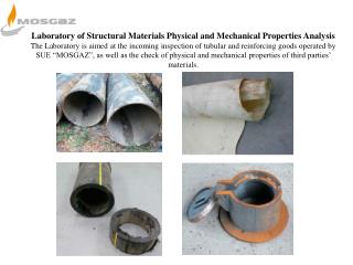
Atomisation of an alloy R. Lindau, FZK, GETMAT project P91 steel SEM of atomized powder Powder sieving
Photo attritor + parameters R. Lindau, FZK, GETMAT project alloying parameters - powder to ball ratio - milling energy (-> rpm, cycling) - milling time
Hot extrusion Y de Carlan, CEA Hot extrusion ODS steel soft steel
What happens during the process ? Mechanical alloying Consolidation 12h milling – With Ti 200nm 12h millingno Ti Before milling nano clusters< 10 nm After milling Fe-18Cr-Ti Y2O3 , Y. De Carlan et al., ICRFM13, 2007
What happens during the process ? Study by X Ray diffraction : Pre-alloyed powder + 10% of yttria M. Ratti et al., Boston, MRS 2008
7000 6000 5000 48h milling with titanium 4000 48h milling without titanium Nombre de coups 3000 2000 1000 0 Angle 2.Théta 26 31 36 41 46 51 What happens during the process? Study by X Ray diffraction : Pre-alloyed powder + 10% of yttria Fe peak After MA After MA After 1h @950°C M. Ratti et al., Boston, MRS 2008
Characterization by Tomographic Atom Probe Consolidation 1100°C M.K. Miller, D.T. Hoelzer, E.A. Kenik, K.F. Russell, Nanometer scale precipitation in ferritic MA/ODS alloy MA957,Journal of nuclear materials 2004 UT -BAT T EL L E O ak Ridge National Laboratory, U .S . Department of Energy D. Hoelzer After mechanical alloying After consolidation 14
Alternative process routes M. Inoue, JAEA
Alternative process routes OCAS, GETMAT project
Optical microscopy • General microstructure Optical micrographs of the general microstructure of MA957 in the (a) as- received condition and after annealing at 1300°C for (b) 1 h and (c) 24 h M.K. Miller et al., JNM 329–333 (2004) 338–341
0.85 W 0.46 Y 0.3 Ti SEM, EDX and microprobe • Grain size and morphology • Structure homogeneity SEM picture of MA957 recrystallized grains obtained after deformation by cold-drawing and recrystallization heat treatment at 1100°C Microprobe analysis of as-manufactured Fe-18Cr-Ti-Y2O3 alloy Y de Carlan, CEA A. Alamo et al., JNM 329–333 (2004) 333–337, CEA
TEM 12Y1 ODS steel: bright- and dark-field TEM micrographs taken near beam direction B ~(1 2 2) Y2O3 particle sizes are in the range of a few tens of nanometers in diameter I.-S. Kim et al., JNM 280 (2000) 264-274
Atom Probe Nanometer scale precipitation in ferritic MA/ODS alloy MA957 after hot consolidation M.K. Miller et al., JNM, 2004 21
Analysis by XRD and SANS • Nature of crystallized phases • Particles size and distribution SANS of ODS steels with 0.3%Y2O3 and 10%Ti at RT under magnetic field (2 Teslas) perpendicular to the incident neutron beam direction, in a range of scattering vectors going from 0 to 0.16 nm-1 XRD of ODS steels with 0.3%Y2O3 and 10% Ti major peak of Fe according to ICDD db M. Ratti et al., Boston, MRS, 2008, CEA M. Ratti et al., ICRFM13, 2007
Ti is the most effective element to refine the dispersoid sizes Precipitation of Ti-Y-O (C) nanoscale clusters Chemical composition: Minor Alloying Elements Refinement of dispersoids size by Minor Alloying Elements AP-FIM with 3D mapping MA/ODS12-YWT Larson D.J. et al., Scripta Mater. 44 (2001) 359-364, ORNL Inoue M., JAEA, MATGENIV, 2007
Chemical composition: Y2O3 content • Effect of addition of Y2O3 in 13Cr-3W-0.5Ti on tensile properties at 650°C • Effect of addition of Y2O3 in 13Cr-3W-0.5Ti on creep rupture strength at 650°C Ukai S., JNM 204 (1993) 65-73
Chemical composition: Minor Alloying Elements • Effect of addition of Ti in 13Cr-3W-0.5Y2O3 on creep rupture strength at 650°C Fig 4 Ukai JNM 1993 Ukai S., JNM 204 (1993) 65-73
Chemical composition: Excess of oxygen • Effect of excess O in 13Cr-3W-0.5Ti-0.5Y2O3 on creep rupture strength at 650°C Ukai S., JNM 204 (1993) 65-73
Effect of the grain size • Effect of MA957 ODS-alloy microstructure on • the impact properties • the tensile properties fine grain A. Alamo et al. , JNM 329–333 (2004) 333–337
Creep properties (creep rupture time) A. Alamo et al., JNM 329–333 (2004) 333–337
Basis of welding • Welding of two metallic pieces= creation of a metal bond between the atoms of the 2 parts • Weld must be as mechanically strong as the base metal • HT strength is due to the uniform dispersion of nanoscale oxide particles welding operation has to retain the nanostructure • no reallocation of the dispersoids • no aggregation of the dispersoids • no change in the initial microstructure liquid state welding solid state welding arnaud.monnier@cea.fr
Liquid state welding melting of the base metal change in the microstructure • Arc welding: • GTAW (Gas Tungsten Arc Welding) • GMAW (Gas Metal Arc Welding):MIG (Metal Inert Gas) or MAG (Metal Active Gas) • Electron beam welding, laser welding GTAW welder (2) GTAW principle (2) GTAW equipment (1) GMAW (1) (1) CEA/DEN/DANS/DM2S/SEMT/LTA (2) www.wikipedia.com GTAW weld in narrow gap (1) electron beam equipment (1)
Solid state wedling Solid state welding retain the microstructure • Solid state welding+ nuclear constraints: large scale, glove box working • HIP (Hot Isostatic Pressing) • SPS (Spark Plasma Sintering) • Friction Stir Welding, Resistance Welding FSW principle (6) Resistance welding principle (4) SPS principle (3) (3) www.ceramicindustry.com (4) www.swantec.com Resistance welding operation (5) (5) www.plasmo.eu (6) www.wikipedia.com
Hot Isostatic Pressure • Surface conditioning: • Degreasing, acid cleaning, mechanical cleaning, ionic sputtering, coating… • Canning: • in a steel capsule (welded by GTAW) • Degassing of the can (P ~ 10-5 mbar) • Closing of the can, gas-tightness • HIP cycling : ~1000 °C/1000 bar/1 h • Removal of the can: • machining, chemical dissolution emmanuel.rigal@cea.fr
High Isostatic Pressing Mockup: upper plate emmanuel.rigal@cea.fr Mockup: first wall Mockup: cooling plate Eurofer joint
Spark Plasma Sintering (SPS) raphael.couturier@cea.fr, CEA Université de Bourgogne SPS principle INSA Lyon
Resistance welding www.cea.fr Resistance welding device of CEA/DEN/DANS/DM2S/SEMT/LTA arnaud.monnier@cea.fr
Resistance welding – characterization of the weld • hardness of the weld = hardness of the base metal • needs for accurate analysis of the dispersoid size and allocation arnaud.monnier@cea.fr
Characterization of ODS weld • How to characterize an ODS weld? • Usual methods to characterize a weld • SEM, EDS analysis, hardness profile • Do not allow observing nanoscale dispersoids • Methods to characterize an ODS • TEM, nano-indentation, SANS • Do not allow checking for the weld homogeneity • + technically difficult to perform
Example of commercial ODS chromia-forming alumina-forming
Y is a RE !!! • Improve the oxidation and corrosion properties longer service life • RE = Reactive Elementeffective when added as • metal or alloy • oxide dispersoids (ODS) • ionic implantation • surface coating Fe-24Cr 800°C, air
alumina scale spalls out protection is lost 12Cr-2W ODS (0.24 Y2O3) FMS 12Cr-2W Oxidation in dry air at 650°C for 2000hrs Improvement of the oxidation properties • Surface oxide thickness • Mass gain • Spallation
Influence on the scale formation Chromia forming Alumina forming • Decrease of the critical Cr% for chromia formation • Promote -Al2O3 (no transitory θ-Al2O3) • Decreases the duration of transitory oxidation(reduces the base metal oxidation) 12Cr steel oxidized at 1300°C in dry air for 50h
O2 O2 O Cr no Y Wagner theory O2 O Y2O3 ox ox2 t t Influence on the scale growth Chromia forming Alumina forming • Supress outward diffusion of metal cation • Decrease the oxidation rate (parabolic constant) • Possible change in the oxidation kinetics (from parabolic to subparabolic)
2µm Influence on the scale microstructure and adhesion Chromia forming Alumina forming • Increase adhesion spallation resistance • Increase the scale compacity and decrease the oxide grain size • Supress the pores at the alloy/scale interface FeCrAl oxidized at 1300°C for 100h Al2O3 dispersion Tb4O7 dispersion
Which is the optimum RE quantity? • No practical rule • It depends on • Chemical nature of the RE • Size and distribution • Chemical interactionwith Ti, C, N • Fabrication technique
Temperature range for ODS use Fe-Cr-Al Ni-Cr Ni-Cr-Al Fe-Cr 800°C 950°C 1200°C 1300°C evaporation oxidation rate spallation spallation breakaway oxidation breakaway oxidation Fe-12Cr evaporation PM2000 tested in air at 1200°C for 1825 h, cycling at RT every 48h