Download
1 / 21
220 likes | 474 Vues
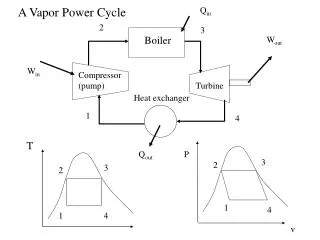
Irreversibilities : Turbine to Condenser-II. P M V Subbarao Professor Mechanical Engineering Department I I T Delhi. Loss in Capacity of Turbine & Increase in Capacity of Condenser…. Irreversible Adiabatic Flow Through Turbine : SSSF. in. h 0. exitactual. exitiso. s.

E N D
Irreversibilities : Turbine to Condenser-II P M V Subbarao Professor Mechanical Engineering Department I I T Delhi Loss in Capacity of Turbine & Increase in Capacity of Condenser….
Irreversible Adiabatic Flow Through Turbine : SSSF in h0 exitactual exitiso s Ideal work wiso = h0in – h0exitiso Actual work wact = h0in – h0exitact Internal Efficiency of a turbine
Losses in Turbine Stage • Losses in Regulating valves : The magnitude of loss of pressure due to throttling with the regulating valves fully open is: • Dpv = 3 to 5% of pmax. • Loss in nozzle blades. • pressure loss in moving blades. • Loss due to exit velocity. • Loss due to friction of the disc and blade banding • Loss associated with partial admission. • Loss due to steam leakages through clearances. • Loss due to flow of wet steam. • Loss due to exhaust piping. • Loss due to steam leakage in seals.
Losses in Nozzles • Losses of kinetic energy of steam while flowing through nozzles or guide blade passages are caused because of • Energy losses of steam before entering the nozzles, • Frictional resistance of the nozzles walls, • Viscous friction between steam molecules, • Deflection of the flow, • Growth of boundary layer, • Turbulence in the Wake and • Losses at the roof and floor of the nozzles. • These losses are accounted by the velocity coefficient, f.
Irreversible Flow Turbine Exit to Condenser P M V Subbarao Professor Mechanical Engineering Department I I T Delhi Irreversibilities due to Closed Cycle Policy …..
LP Turbine Exhaust System • In a condensing steam turbine, the low-pressure exhaust hood, consisting of a diffuser and a collector or volute!, connects the last stage turbine and the condenser. • The function of the hood is to transfer the turbine leaving kinetic energy to potential energy while guiding the flow from the turbine exit plane to the condenser. • Most of exhaust hoods discharge towards the downward condenser. • Flow inside the hood therefore must turn about 90 deg from the axial direction to the radial direction before exhausting into the condenser. • The 90-deg turning results in vortical flow in the upper half part of the collector and also high losses. • The exhaust hood is one of the few steam turbine components that has the considerable aerodynamic losses. • It is a challenge for engineers to operate a hood with high pressure recovery and low total pressure loss in a compact axial length.
Steam Turbine Exhaust Size Selection • The steam leaving the last stage of a condensing steam turbine can carry considerably useful power to the condenser as kinetic energy. • The turbine performance analysis needs to identify an exhaust area for a particular load that provides a balance between exhaust loss and capital investment in turbine equipment.
Residual velocity loss Steam leaving the last stage of the turbine has certain velocity, which represent the amount of kinetic energy that cannot be imparted to the turbine shaft and thus it is wasted Exhaust end loss Exhaust end loss occur between the last stage of low pressure turbine and condenser inlet. 2. Exhaust loss depends on the absolute steam velocity. Turbine Exhaust end loss = Expansion-line -end point - Used energy at end point.
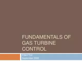
Typical exhaust loss curve showing distribution of component loss Annulus restriction loss Total Exhaust Loss SP.Volume Annulus velocity (m/s) Turn-up loss Condenser flow rate Gross hood loss Annulus area Actual leaving loss Percentage of Moisture at the Expansion line end point 50 40 Exhaust Loss, kJ/kg of dry flow 30 20 10 0 120 240 180 240 300 360 Annulus Velocity (m/s)