Download
1 / 21
220 likes | 510 Vues
An FPGA-Based Adaptive Computing Implementation of Chirp Signal Detection. by J. Zaino, R. Bassett, T.S. Sun, J.M. Smith, E. Pauer, S. Kintigh, D.W. Tufts. Presented by: John C. Zaino (603) 885-5836 john.c.zaino@lmco.com.

E N D
An FPGA-Based Adaptive Computing Implementation of Chirp Signal Detection by J. Zaino, R. Bassett, T.S. Sun, J.M. Smith, E. Pauer, S. Kintigh, D.W. Tufts Presented by: John C. Zaino (603) 885-5836 john.c.zaino@lmco.com
An FPGA Based Adaptive Computing Implementation of Chirp Signal Detection • RAAC Program at Sanders, a Lockheed Martin Co. • Objectives: Investigate innovative algorithms, approaches, and new mathematical techniques that exploit the unique capabilities of Adaptive Computing Systems (ACS) • Investigate requirements of transient signal analysis applications, candidate algorithms, and their suitability for ACS processing • Exploit ACS for improved speed/performance (e.g. EW and RF systems) • Investigate performance and sizing trades in ACS implementations, and demonstrate them in software simulations and ACS testbeds • Semi-coherent detection technology implemented in an FPGA based testbed • Performed comparison of single pulse performance versus computational complexity of various coherent and incoherent linear FM detection approaches: evaluation of limitations versus best approach - applicability to adaptive computing • Developed mathematical model for calculation of SNR gain for semi-coherent detection of linear FM signals • Powerful approach to rapid iterative ACS algorithm analysis and visualization using ACS tools and implementations to effectively target and refine a design
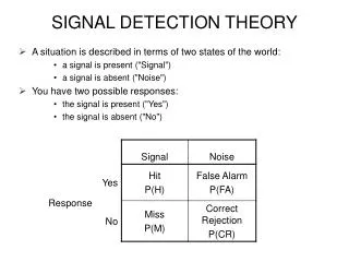
Signal Detection Techniques Unknown Signal + Noise Detect Classify • Signal transformation SNR & Change Domain for Detection/Estimation • Peak Detection • Parameter Estimation Pulse or CW: A exp[j(wt + bt2 )] for tn<t < tn+T and tn = ntPRI Where: A = complex amplitude w = the starting frequency b = the chirp rate T = the pulse width, and tPRI = the pulse repetition period Performance f(probability of detection(pd) for a False Alarm Rate (FAR) + measurement accuracy (w, b, T, tPRI))
FM SIGNAL DETECTION TECHNIQUES • Investigated 5 Methods • Least Squares Method • Hough Transform Method • Wigner Distribution Function Method • Chirp-Matched Filter Method • Semi-coherent Processing Method
FM Signal Detection Techniques • Least Squares Method • Relatively efficient (FFT major process load) • Chirp rate and starting frequency estimated directly • Useful if dominant signal in field • Multiple signal interference • Lowest processing gain • Hough Transform Method • Widely used to enhance detection of linear structures in image data • Maps point on line to single point in transform domain • Processing efficiency nearly same as least squares if proper choice of control threshold • Detection of multiple signals (well separated in parameter space) • Less accurate and multiple source interference if close in parameter space • Wigner Distribution Function Method • Same process as Hough Transform Method except WDF generation replaces Short-time FFT • Bilinear transformation which involves Fourier transform of product of a delayed copy and conjugate of an advanced copy of signal • Improved performance in detection probability and estimation accuracy • Significant increase in computations • Performance affected by cross-spectra in generation of WDF if two signals correlated inside the window
FM Signal Detection Techniques (cont’d) • Chirp-Matched Filter Method • Bank of filters generated from chirp wave forms • Sufficient to “de-chirp” any input signal in expected range • Nearly optimal coherent processing gain (best of 5 methods) • Detection and estimation most robust with multiple sources • Most computationally expensive (control # filters and size of time increments) • Output contains monotone signal with: frequency of (2bt). t is the delay time = beat frequency between the signal and its delayed copy • In the absence of noise = output from a perfectly matched chirp filter • Performance efficient and approaches to the coherent result as the SNR increases • Accurate chirp rate b determined immediately by performing FFT to the product sequence • Less accurate frequency estimation • Susceptible to multiple source interference -non-vanishing cross products in first steps-overcome with algorithm design and careful analysis of mutual frequency relationship • Semi-coherent Processing Method • Non-linear transform involving product of input signal with conjugate of delayed copy of itself, i.e., x(t) x*(t-t)
Semi-coherent Method of FM Signal Detection • Method/Theoretical Framework • Attributes of PDF and Empirical Models • MATLAB Demo of Detection and False Alarm Performance
Semi-coherent Method of FM Signal Detection • Probability Distribution Function (PDF) of Semi-coherent Processing Output • Predicting detection performance • Finding optimal values of processing parameters • Theoretical Framework • Output of first stage of semi-coherent method:y(tm, wk) = S x(tn) x*(tn-tm) exp(-jwktn) • Input: x(t) = s(t) + n(t)(deterministic signal and a complex gaussian random noise) • The probability density (PDF) of normalized | y(tm, wk)| for any given value of rin can be derived as follows: • where: R(r,g) = joint probability density of the magnitude and the angle of the complex-valued random variable y(tm, wk), and P(r) = desired PDF, evaluated with respect to the normalized magnitude r and Real and Imaginary parts assumed mutually independent, each with variances2 SNRInput = rin = A2/(2s2) • NS = # terms in summation and • MD = length of delay
Attributes of PDF and Empirical Models (Practical) • Approximate w/simple analytic functions for certain range of rin • P(r) - No closed form - Must compute for each value of r and for each input SNR • In the limit rin = 0 • P(r) can be placed by a Rayleigh function • PFA = exp[-g2/(2s12)] g = s1[-2 ln(PFA)] 1/2 • For a wide range of rin > 0 • P(r) can be approximated by a Gaussian function with a unity mean • PD~ 0.5[1 - erf( u )]where u = g/(21/2s2) - rout1/2 (False Alarm Threshold) Processing Gain Output SNR vs. Input SNR • Output SNR - use simple empirical model for wide range of rin • rout = NS rin /(C + 1/rin) with 2 < C < 4 • Value of C depends on • NS = # terms in summation and • MD = length of delay and must be determined empirically or computed using the equations of P(r) SNROut = N* SNRIn /(C+1/ SNRIn) C = 2.9383 N = 128 pt FFT MATLAB Simulation * Output SNR Input SNR
Validation: Formula vs MATLAB Circuit Simulation Input SNR = -4 dB N = 128 pt FFT Threshold (Pd = 0.95, Pfa = 0.001) Pd Probability Density Pfa Noise Signal + Noise Processed Magnitude (Single Bin) MATLAB Demo of Detection and False Alarm Performance • Conducted two experiments to demonstrate validity of empirical models using MATLAB simulation • 104 simulation runs • 1st Experiment • constant threshold derived from empirical model • simulation PDandPFA slightly higher than empirical • 2nd Experiment • varied threshold and measured PDandPFA • model predictions excellent agreement with simulation results
Linear FM Chirp Processing Implementation • SparcStation 30 with PCI Bus • Annapolis Microsystems Wildforce Module (FPGAs) • Integrated into workstation and DARPA funded ACS Ptolemy tools (Algorithm Analysis and Mapping Environment program) for GUI and implementation aspects
Linear FM Chirp Processing Implementation (cont’d) • Design goal: 25 MSamples/sec complex data (16-bit I/Q pairs) of linear FM chirped signals • Algorithm decomposed to components of: Non-FFT (on Wildforce FPGA Board(Xilinx 4062 XL) Delay, Complex Conjugate, Complex Multiply FFT (on SparcStation 30: 2 FFTs overlapped 50%) Drove waterfall display showing chirp rates • Signal Generators: 3 periodic chirp signals, 1 band-limited analytic noise (Ptolemy “Stars”) • 300 KHz/us • 2.3 MHz/us • 1 MHz/us Chosen for interesting range of chirp rate excursions and pulse widths • Signal Detection • Incoming signal correlated with delayed copy of itself • look for resultant constant differential tones chirped signal present • Approach provided semi-coherent detection integration across overlapped delayed & incoming signal
FIFO PCI Ext I/O M1 M2 M3 M4 FIFO PE1 PE2 PE3 PE4 M0 FIFO PE0 INTERCONNECT Connect Linear FM Chirp Processing Implementation (cont’d) FPGA Segment • 2 Configurations • Configuration 1 • Single processing element (PE) FPGA • First hardware implementation • Board operated at 35 MHz • 5 clock cycles/16-bit I/Q pair (32-bit sample) • serial implementation required for all I/O and algorithm processing • Multiple PEs (All 5 FPGAs on Wildforce board) • Required development of crossbar and systolic interconnect modeling techniques by the Sander’s Algorithm Analysis and Mapping program • Achieved 40 MHz processing speed • 1 clock cycle/I/Q pair Stream data from Wildforce memory @ 40 MSamples/sec
Linear FM Chirp Processing Implementation (cont’d) FPGA Development • Developed using Adaptive Computing System tools generated by DARPA funded Algorithm Analysis and Mapping tools • Ptolemy “Stars” (function blocks) and tools scheduling capability in Synchronous Data Flow (SDF) domain data transfer to/from Wildforce module memory • Developed driver interface between Wildforce board and Ptolemy (workstation) environment • Data streaming on Wildforce • Data Blocks • I/O: PCI bus connector versus dedicated transfer ports/main memory access • Production accelerated system: modify - e.g. for main memory I/O, optimum block sizes, dedicated point-to-point communication bus • 4K data block size for final demo demonstrated full rate processing with short time delay for generation of output graphics displays in Ptolemy (multiple block processing selectable at runtime) • Larger block sizes during development stages for timing & validiations with Matlab and a DOD Signal Processing Library package Wildforce FPGA Board Input Data File PE Assoc’d memory Full rate processing PE Assoc’d memory Output File
Linear FM Chirp Processing Implementation (cont’d) FPGA Development (cont’d) • FPGA Components • Delay Element set @ 25 samples • min criteria: Just enough delay to make differential tone appear around 2nd bin of output FFT for signals @ slowest chirp rate • max criteria: Ensure at least one set of overlapped pulse data processed by FFT for min expected pulse width • FFT size and amount of overlapped FFT processing also a factor • More highly overlapped FFTs requires increased # of FFTs and operate concurrently • Production system: May employ bank of different delays and replicas of complete FPGA circuit to process wide range of chirp rates in parallel
ACS Algorithm Analysis and Mapping Tools (Ptolemy SDF Domain) 25 MS/S 16-Bit I/Q Pairs 300 KHz/ms 1 MHz/ms 2.3 MHz/ms Noise ACS Tools (VHDL Code Generator) Linear FM Chirp Processing Implementation (cont’d) FPGA Development Flow • FPGA segments initially simulated in Ptolemy “Stars” to test other Ptolemy elements of demonstration • Ptolemy hardware description then developed • 4 multipliers • 1 adder • 1 subtractor • VHDL code generation from hardware description • Feature of Algorithm Analysis and Mapping Environment ACS tools • Conducted place & route on FPGA(s) • Substitution of Ptolemy algorithm section with Wildforce driver for FPGA communication and accelerated processing Hardware Model ACS Developed FPGA Driver VHDL Code
RAAC Enhancements toSander’s ACS PtolemyTools • Ram Delay Smart Generator • FPGA CLB’s as RAMS for signal delay - 2 to 600 clock period delays via Xilinx Core generators • Significant CLB count reduction over traditional delays using registers • Multiplication Smart Generator • Wrapper smart generator invokes Xilinx core generator • Annapolis Wildforce Timing • Ptolemy Wildforce FPGA controller star augmented for timing calcs to one clock period (2.5 to 50 MHz) • Crossbar and systolic interconnect modeling techniques developed for multiple FPGA use
Demonstration Results • Techniques illustrated provide: • Capability to enhance detection and measurement SNR by 10 to 20 dB (depending on signal pulse widths and excursions) while • Processing input data at real time rates in hardware up to 40 MSamples/sec Noisy Chirp Signal Clear Tone Detection • Achieved Wildforce processing speed • Single PE (FPGA) 35 MHz & 5 clock cycles per I/Q sample pair (16-bit I&Q) • Multiple Pes (5 FPGAs) 40 MHz & 1 clock cycle per I/Q pair 40 MSamples/sec data streaming from onboard memory
Demonstration Results (cont’d) • Matlab simulations verified • Ptolemy software (hardware simulation in Ptolemy “stars”) + Actual hardware implementation of algorithm for detection of chirped FM signal • Additional verification of processing results using separate DOD signal processing library package • Multiplatform validation • High assurrance of techniques developed • Validated architecture Matlab simulated output also matched Matlab spectrogram of FPGA hardware output