Download
1 / 111
1.15k likes | 1.5k Vues
Sequence Diagram & Pattern Visitor. California State University , Los Angeles Dr. Jiang Guo Fall 2010 Presented by : Sanaz Bonakdar Behin Behdinian Kate Dehbashi Amee Joshi Monali Bhavsar. Sequence Diagram. Sequence Diagram Sanaz Bonakdar Behin Behdinian Kate Dehbashi. Outline.

E N D
Sequence Diagram&Pattern Visitor California State University , Los Angeles Dr. Jiang Guo Fall 2010 Presented by : Sanaz Bonakdar Behin Behdinian Kate Dehbashi Amee Joshi Monali Bhavsar
Sequence Diagram • Sequence Diagram • Sanaz Bonakdar • Behin Behdinian • Kate Dehbashi
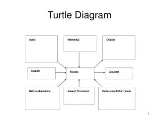
Outline • Sequence Diagram Elements • Loops and Conditional • Video example on creating SD in Eclipse • Synchronous and Asynchronous call • Sequence Diagram Application • The Logic of Method • System Sequence Diagram • Actor • System Events • System Operation • Use Case
Introduction • The sequence diagram is one of the interaction diagrams • Shows the interactions between objects in the sequential order • It captures the behavior of a single scenario • Shows a number of objects and the messages that are passed between these objects within the use case • Its useful in documenting how a future system should behave • It can be used in the transition from requirements expressed as use cases to the next and more formal level of refinement.
The Basics • The main purpose of a sequence diagram is to define event sequences that result in some desired outcome. • The focus is less on messages themselves and more on the order in which messages occur • The diagram conveys this information along the horizontal and vertical dimensions • The vertical dimension shows, top down, the time sequence of messages/calls as they occur • The horizontal dimension shows, left to right, the object instances that the messages are sent to.
Sequence Diagram Elements Participant • Columns = Object • Arrows = messages • Narrow rectangles = activations • Dashed lines = lifelines • Column fuller syntax name : Class • Both the name and the class name are optional, but must keep the colon if use the class. • Called found message= The first message doesn’t have a participant. Activation Found Message Message Lifeline
Frame • Frame • The frame element is used as a basis for many other diagram elements in UML 2 • It provides a consistent place for a diagram's label • The frame element is optional in UML diagrams • The format of using Frame : Diagram Type Diagram Name
Lifelines • Lifelines • Lifeline notation elements are placed across the top of the diagram • Lifelines are drawn as a box with a dashed line descending from the center of the bottom edge. The lifeline's name is placed inside the box. • Lifelines represent either roles or object instances that participate in the sequence being modeled . • The UML standard for naming a lifeline follows the format of : • Instance Name : Class Name Figure 1: An example of the Student class used in a lifeline whose instance name is freshman
Message • The first message of a sequence diagram always starts at the top and is typically located on the left side of the diagram • Subsequent messages are then added to the diagram slightly lower then the previous message. • Solid arrowhead (synchronous call operation ) or stick arrowhead (asynchronous signal ):To show an object (i.e., lifeline) sending a message to another object • The message/method name is placed above the arrowed line . • Dotted line is return message and its optional
Figure 2 Figure 2: An example of messages being sent between objects
Figure 2 • In the example in Figure 2, the analyst object makes a call to the system object which is an instance of the ReportingSystem class by getAvailableReports method. • The system object then calls the getSecurityClearance method with the argument of userId on the secSystem object • The secSystem object returns userClearance to the system object when the getSecurityClearance method is called • The system object returns availableReports when the getAvailableReports method is called.
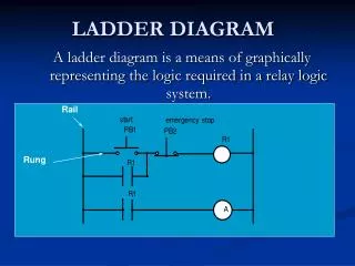
Guard • Guards are used throughout UML diagrams to control flow • We placed the guard element above the message line being guarded and in front of the message name. Guard
Loops And Conditional • Sequence diagrams also can show the looping and conditional behavior. • Treat sequence diagrams as a visualization of how objects interact rather than as a way of modeling control logic. • Both loops and conditionals use interaction frames ,which are ways of marking off a piece of a sequence diagram. • Frames consist of some region of a sequence diagrams that is divided into one or more fragments. • Each frame has an operators • Each fragment may have a guard
Loops And Conditional • To show a loop, we use the loop operator with a single fragment and put the basis of the interaction in the guard • alt : For conditional logic, we can use an alt operator and put a condition on each fragment. Only the fragment whose guard is true will execute. (classic "if then else" logic ) • opt : The option combination fragment is used to model a sequence that, given a certain condition, will occur; otherwise, the sequence does not occur. An option is used to model a simple "if then" statement • Other operators: • par :indicates that the associated interaction fragments are executed in parallel • region:A critical region takes precedence over any other enclosing fragments and does not allow other traces on any lifeline contained within the fragment to be executing at the same time • ref : refers to an interaction defined on another diagram.
Figure 8 • Figure 8 indicate looping logic. One way is to show a frame with the label loop and a constraint indicating what is being looped through, such as for each seminar . • Figure8 includes an asynchronous message, the message to the system printer which has the partial arrowhead. An asynchronous message is one where the sender doesn’t wait for the result of the message, instead it processes the result when and if it ever comes back. • Up until this point all other messages have been synchronous, messages where the sender waits for the result before continuing on.
Create Sequence Diagram in Eclipse • How to create Create Sequence Diagram in Eclipse ?
Sequence Diagram • Synchronous and Asynchronous call
Synchronous call • If a caller sends a synchronous message, it must wait until the message is done, A message that is sent synchronously assumes that the receiver is ready and listening and the caller waits for the completion of the operation and the return. It does not continue with the next steps in its execution until the receipt of a return. -invoking a subroutine. -ATM
Asynchronous call • If a caller sends an asynchronous message, itcan continue processing and doesn’t have to wait for response. • Asynchronous calls can be found in multithreaded applications and in message oriented middleware. • Asynchronous gives better responsiveness and reduces the temporal coupling but is harder to debug.(Temporal coupling refers to the degree to which the sending and handling of a message are connected in time)
Sequence Diagram Observations • UML sequence diagram represent behavior in terms of interactions. • They complement class diagrams, which represent structure. • Useful for finding participating objects.
Comparison with other Diagrams • Sequence diagram • State diagram • Activity diagram • Communication diagram • Timing diagram • …
Sequence diagram • Use sequence diagrams when we want to look at the behavior of several objects within a single use case.
State diagram • Use state diagrams when we want to look at the behavior of a single object across many use cases.
Activity diagram • Use activity diagrams when we want to look at the behavior across many use cases or many threads.
Sequence Diagram Application Sequence diagrams are typically used to model • Usage scenario • The logic of method • The logic of Services
Sequence Diagram Application(I) • Usage Scenarios. A usage scenario is a description of a potential way your system is used. • The logic of usage scenario may be part of a use case, perhaps an alternate course. It may also be one entire pass through a use case, such as the logic described by the basic course of action or a portion of the basic course of action, plus one or more alternate scenarios. The logic of a usage scenario may also be a pass through the logic contained in several use cases.
Sequence Diagram Application(I) Fund available: withrawcash Withdraw cash Insufficient fund: Withdraw cash Card Holder
Sequence Diagram Applications • The logic of methods Sequence diagrams Can be used to explore the logic of a complex operation, function, or procedure. One way to think of sequence diagrams, particularly highly detailed diagrams, is as visual object code.
The Logic of Method aStudent:Student :Seminar :Course enrollStudent(aStudent) isStudentEligible(aStudent) getSeminarHistory() seminarHistory Eligibility Status enrollmentStatus
Sequence Diagram Application • The Logic of Services A service is effectively a high-level method, often one that can be invoked by a wide variety of clients. This includes web-services as well as business transactions implemented by a variety of technologies such as CORBA-Compliant Object Request Brokers(ORBs).
DB (vector of student object) Enroll in seminar Use case student Persistance framework Exsist(name,address,phone) Build SQL Select Search(student,name,address,phone) Select statement List of all potential matches Result set Student data structure
The Logic of Method aStudent:Student :Seminar :Course enrollStudent(aStudent) isStudentEligible(aStudent) getSeminarHistory() seminarHistory Eligibility Status enrollmentStatus
Basic course of action: • The student wants to enroll in a seminar. • The student inputs his name and student number into the system • The system verifies that the student is eligible to enroll in seminars • The system displays the list of available seminars. • The student indicates the seminar in which he wants to enroll. • The system validates that the student is eligible to enroll in the seminar • The system validates that the seminar fits into the existing schedule of the student • The system calculates the fees for the seminar • The system displays the fees • The system asks the student whether he still wants to enroll in the seminar. • The student indicates that he wants to enroll in the seminar. • The system enrolls the student in the seminar.
Continue.. 13. The system informs the student the enrollment was successful 14. The system bills the student for the seminar 15. The system asks the student if he wants a printed statement of the enrollment. 16. The student indicates that he does want a printed statement. 17. The system prints the enrollment statement 18. The use case ends when the student takes the printed statement.
Alternate course A: The student is not eligible to enroll in seminars • The system determines the student is not eligible to enroll in seminars. • The system informs the student he is not eligible to enroll. • The use case ends.
Alternate course B The student does not have the prerequisites • The system determines that the student is not eligible to enroll in the seminar he has chosen. • The system informs the student that he does not have the prerequisites. • The system informs the student of the prerequisites he needs. • The use case continues at Step 4 in the basic course of action.
Alternate course C The student decides not to enroll in an available seminar • The student views the list of seminars and doesn't see one in which he wants to enroll. • The use case ends.
Sequence Diagram • System Sequence Diagram (SSD)
System Sequence Diagram (SSD) - Example Example Online Shopping Shopping in the store
System Sequence Diagram (SSD) - Actor • Actor • Specifies a role played by a user or any other system that interacts with the system • Generates events to a system, requesting some operation in response • Actors may represent roles played by human users, external hardware, or other subjects • UML 2 does not permit associations between Actors
System Sequence Diagram (SSD) – System Events • System Event • External event • Generated by an actor • Directly stimulates the system • To identify system events, it is necessary to be clear on the choice of system boundry • Example: customer chooses an item for purchase (ProductID, amount) Item#456464646 Qty.1
System Sequence Diagram (SSD) – System Operation • System operation • Operation of the system • Executes in response to a system event • Example: System generates an invoice (inv#,description,total amount) Inv#6354254765
System Sequence Diagram (SSD) – Use Case • Use Case • Description of a system’s behavior as it responds to a request that originates from outside of that system • “Who" can do "what" with the system • Suggests how actors interact with the system • Use cases treat the system as a black box • Should be constructed by business domain knowledgeable people • A use case may show one or more (more commonly more…) use case scenarios