Download
1 / 46
540 likes | 1.01k Vues
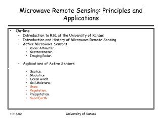
Passive Microwave Remote Sensing. Outline for 22 Feb 2008. Passive Microwave Radiometry Active microwave remote sensing. Passive Microwave Radiometry. Microwave region: 1-200 GHz (0.15-30cm) Uses the same principles as thermal remote sensing Multi-frequency/multi-polarization sensing

E N D
Outline for 22 Feb 2008 • Passive Microwave Radiometry • Active microwave remote sensing
Passive Microwave Radiometry • Microwave region: 1-200 GHz (0.15-30cm) • Uses the same principles as thermal remote sensing • Multi-frequency/multi-polarization sensing • Weak energy source so need large IFOV and wide bands
Microwave Brightness Temperature • Microwave radiometers can measure the emitted spectral radiance received (Ll) • This is called the brightness temperature and is linearly related to the kinetic temperature of the surface • The Rayleigh-Jeans approximation provides a simple linear relationship between measured spectral radiance temperature and emissivity
At long wavelengths, such as in the microwave region, the relationship between spectral emittance and wavelength can be approximated by a straight line.
Rayleigh-Jeans Approximation a constant • k is Planck’s constant, c is the speed of light, e is emissivity, T is kinetic temperature • This approximation only holds for l >> lmax • (e.g. l > 2.57mm @300 K) spectral radiance is a linear function of kinetic temperature
Brightness Temperature eTis also called the “brightness temperature” typically shown as TB
Brightness temperature can be related to kinetic temperature through emissivity Thus, passive microwave brightness temperatures can be used to monitor temperature as well as properties related to emissivity
Microwave Radiometers • Advanced Microwave Sounding Unit (AMSU) 1978-present • Scanning Multichannel Microwave Radiometer (SMMR) 1981- 1987 • Special Sensor Microwave/Imager (SSM/I) 1987-present • Tropical Rainfall Measuring Mission (TRMM) 1997-present • Advanced Microwave Scanning Radiometer (AMSR-E) 2002-present
Passive Microwave Radiometry • Passive microwave sensors use an antenna (“horn”) to detect photons at microwave frequencies which are then converted to voltages in a circuit • Scanning microwave radiometers • mechanical rotation of mirror focuses microwave energy onto horns
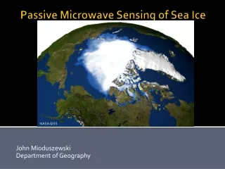
Passive Microwave Applications • Soil moisture • Snow water equivalent • Sea/lake ice extent, concentration and type • Sea surface temperature • Atmospheric water vapor • Surface wind speed • Cloud liquid water • Rainfall rate only over the oceans
Sea surface temperature Land surface temperature Monitoring Temperatures with Passive Microwave
Passive Microwave Sensing of Land Surface Emissivity Differences • Microwave emissivity is a function of the “dielectric constant” • Most earth materials have a dielectric constant in the range of 1 to 4 (air=1, veg=3, ice=3.2) • Dielectric constant of liquid water is80 • Thus, moisture content affects brightness temperature • Surface roughness also influences emissivity
Dry Snow Soil Snow Emissivity Example brightness temperature (2) dry snow snow water equivalent Wet Snow Soil Soil (1) (3) Wet snow is a strong absorber/emitter
SSM/I Northern Hemisphere snow water equivalent (mm of water)
Atmospheric Effects • At frequencies less than 50 GHz, there’s little effect of clouds and fog on brightness temperature (it “sees through” clouds) • Thus, PM can be used to monitor the land surface under cloudy conditions • In atmospheric absorption bands, PM is used to map water vapor, rain rates, clouds
Atmospheric Mapping • Mapping global water vapor • 85 GHz
Passive Microwave Sensing of Rain • Over the ocean: • Microwave emissivity of rain (liquid water) is about 0.9 • Emissivity of the ocean is much lower (0.5) • Changes in emissivity (as seen by the measured brightness temperature) provide and estimate of surface rain rate • Over the land surface: • Microwave scattering by frozen hydrometeors is used as a measure of rain rate • Physical or empirical models relate the scattering signature to surface rain rates
Rainfall from passive microwave sensors: Accumulated precipitation from the Tropical Rainfall Measuring Mission (TRMM) Similar to SSM/I
Passive Microwave Remote Sensing from Space Advantages Disadvantages • Penetration through non-precipitating clouds • Radiance is linearly related to temperature (i.e. the retrieval is nearly linear) • Highly stable instrument calibration • Global coverage and wide swath • Larger field of views (10-50 km) compared to VIS/IR sensors • Variable emissivity over land • Polar orbiting satellites provide discontinuous temporal coverage at low latitudes (need to create weekly composites)
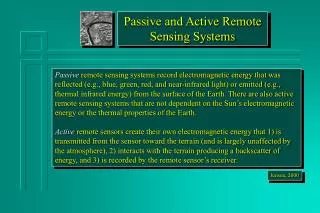
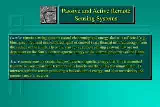
Passive and Active Systems Passive remote sensing systems record electromagnetic energy that is reflected or emitted from the Earth’s surface and atmosphere Active sensors create their own electromagnetic energy that 1) is transmitted from the sensor toward the terrain, 2) interacts with the terrain producing a backscatter of energy, and 3) is recorded by the remote sensor’s receiver.
Radar=Radio Detection and Ranging Radar system components
Radar: How it Works • A directed beam of microwave pulses are transmitted from an antenna • The energy interacts with the terrain and is scattered • The backscattered microwave energy is measured by the antenna • Radar determines the direction and distance of the target from the instrument as well as the backscattering properties of the target
Radar Parameters • Azimuth Direction • direction of travel of aircraft or orbital track of satellite • Range angle • direction of radar illumination, usually perpendicular to azimuth direction • Depression angle • angle between horizontal plane and microwave pulse (near range depression angle > far range depression angle) • Incident angle • angle between microwave pulse and a line perpendicular to the local surface slope • Polarization • linearly polarized microwave energy emitted/received by the sensor (HH, VV, HV, VH)
Radar Nomenclature • Nadir • azimuth flight direction • look direction • range (near and far) • depression angle () • incidence angle () • altitude above-ground-level, H • polarization
Synthetic Aperture Radar • Antenna “length” is increased synthetically by building up a history of backscattered signals from the landscape along the track of the sensor • Implemented by keeping track of the Doppler shift of the reflected signal (frequency of the transmitted signal is known)
Layover occurs when the incidence angle (q) is smaller than the foreslope (a+) i.e., q< a+. This distortion cannot be corrected! Layover
Radar Shadowing Radar shadowing can be useful for interpreting geomorphological features
Power received = Power per unit area at target x Effective scattering area of the target x Spreading loss of reradiated signal x Effective receiving area of antenna Radar Backscatter
Radar Backscatter Coefficient The efficiency the terrain to reflect the radar pulse is termed the “radar cross-section”, The radar cross-section per unit area, (A) is called the “radar backscatter coefficient”(˚) and is computed as : The radar backscatter coefficientdetermines the percentage of electro- magnetic energy reflected back to the radar from within a radar pixel This is similar to the reflectance in optical remote sensing
Radar Backscattering Depends on the properties of the target: • roughness • dielectric constant Depends on characteristics of the radar: • depression angle • frequency/wavelength • polarization
Rayleigh Criterion for Roughness • A surface is considered smooth at or below a height, h, if: [ cm ] h = the vertical relief (average height of surface irregularities) l = the radar wavelength (measured in cm) g = the depression angle
Nile River Sudan Space Shuttle Color-Infrared Photograph SIR-C Color Composite: • Red = C-band HV • Green = L-band HV • Blue = L-band HH C-band, = 6cm L-band, = 24cm
Radar and the Dielectric Constant • Dielectric constant depends on the type of material as well as its moisture state • it is analogous to the refractive index of the material • it is primarily a function of moisture content • also depends on chemical properties such as salinity • Dielectric constant is the ratio of the capacitance of a material to that of a vacuum. Also known as the “relative permittivity”
Dielectric Constant dielectric constant of liquid water is 80; dry soil is 2-4.
Radar frequency and backscatter • Depth of radar penetration through the vegetation canopy varies directly with l
Types of Active Microwave Surface and Volume Scattering that Take Place in a Hypothetical Pine Forest Stand
Response of A Pine Forest Stand to X-, C- and L-band Microwave Energy