Download
1 / 39
650 likes | 1.14k Vues
Lecture 11: Serial Data Communication & 8251. The 80x86 IBM PC and Compatible Computers. Chapter 17 Serial Data Communication and the 8251 Chip. Data Communication.

E N D
The 80x86 IBM PC and Compatible Computers Chapter 17 Serial Data Communication and the 8251 Chip
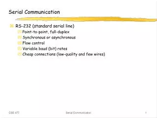
Data Communication • Data transmission is the transfer of data from point-to-point often represented as an electromagnetic signal over a physical communication channel • A communication channel refers to the medium used to convey information from a sender (or transmitter) to a receiver. • Examples: copper wires, optical fibbers or wireless communication channels.
Two Ways: Parallel & Serial • Parallel data transfers: • Each bit uses a separate line (wire) • Often 8 or more lines are used • Control signals in addition • Fast & expensive & for short-distance communication • Serial data transfers: • One single data line • Bits are sent over the line one by one • No dedicated lines for control signals • Cheap & slow & for long-distance communication
Computer Computer Serial interface Serial interface MODEM MODEM channel DCE DCE DTE DTE The Whole Picture of Serial Communication • The sender and receiver need a protocolto make sense of data: • e.g., how the data is packed, how many bits constitute a character, when the data begin and end DTE- Data Terminal Equipment, usually a computer. DCE- Data Communication Equipment, usually a modem. Serial interface–ICs such as 8251A,16550, and 8250, connecting DTEand DCE.
Serial Communication • Data transfer rate • Synchronization methods • Communication modes • Error detection • Modulation and Demodulation
Data Transfer Rate • Symbol rate, a misnomer is baud rate • The number of distinct symbol or pulse changes (signaling events) made to the transmission medium per second in a digitally modulated signal or a line code, quantified using the baud unit • Each symbol can represent one (binary encoded signal) or several bits of data • Bit rate • the number of bits that are conveyed or processed per unit of time, quantified using the bits per second (bit/s or bps) unit
Synchronization Methods • Asynchronous serial communication: • Transfer one byte at a time • The starting of each byte is asynchronous, and therefore each byte needs synchronization between the sender and the receiver using start bit. • Synchronous serial communication: • Transfer a block of data at a time • The sender and the receiver are synchronized at the beginning of data transfer using synch characters.
Synchronous Transmission • Bit stuffing (or zero bit insertion): inserts a “0” after five consecutive 1s • Bit stuffing (or zero bit insertion): inserts a “0” after five consecutive 1s
Communication Modes • Simplex: • Only one way • E.g., printer • Half-duplex: • Data is transmitted one way at a time • E.g., walky-talky • Full-duplex • Data can go both ways at the same time • E.g., telephone
Error Detection • Parity bit • Used in asynchronous serial communication • Put an extra parity bit at the end of each character • Even-parity: the data and the parity bit has an even number of 1s; odd-parity • CRC Calculation • k-bit data, n-bit CRC: • Example: • Given G(x)= x3 + x2 + 1 ->1101, (take the coefficients of the polynomial, n=3) • If data is 1010110, M(x) * Xn -> 1010110000 • CRC = 1010110000%1101 (the remainder of binary division, using XOR operation)
Modulation and Demodulation • It is not suitable to transmit digital signals directly on a channel for a long distance • signal distortion • Need to modulate digital signals and get analog signals at the sender, and demodulate the analog signals and get the original digital signals • Three parameters (Amplitude, frequency, phase) of the carrier can be used for the modulation and demodulation purpose • Amplitude-Modulating (AM) • Frequency-Shift Keying (FSK) • Phase-Shift Keying (PSK)
Modulation and Demodulation 1 and 0 are represented using different amplitude 1 and 0 are represented using different frequency
8251 USART Chip • Capable of doing both asynchronous and synchronous data communication • synchronous: baud rate 0-64K, characters can be 5, 6, 7, or 8 bits, automatically detect or insert sync characters • Asynchronous: baud rate 0-19.2K, characters can be 5, 6, 7, or 8 bits, automatically insert start, stop and parity bits, TxC and RxC clocks can be 1, 16, or 64 times of the baud rate • Full duplex, double-buffered • Error checking circuit
8251 Mode Word Asynchronous Synchronous
8251 Programming Example • Use 8251 to transfer 256 characters in asynchronous mode, assuming that the port addresses are 208H and 209H, the baud factor is 16, and 1 stop bit, 1 start bit, no parity bit, and 8-bit character are used. Solution: Sender side: data is stored in Buf1 LEA DI, Buf1 MOV DX,209H MOV AL,00H ;worse-case init. OUT DX,AL CALL DELAY MOV AL,00H ; OUT DX,AL CALL DELAY MOV AL,00H ; OUT DX,AL CALL DELAY MOV AL,40H ;reset command OUT DX,AL MOV AL,01001110B ; mode word MOV DX,AL MOV AL,00110111B ; command word OUT DX,AL MOV CX,256 ; to send 256 char. NEXT: MOV DX, 209H IN AL,DX ; status word AND AL,01H ; TxRDY? JZ NEXT MOV AL,[DI] MOV DX,208H ; data register 208H OUT DX,AL ; send the char. INC DI LOOP NEXT
8251 Programming Example Receiver side: data will be stored in Buf2 Data segment buf2 DB 256 dup(?) Data ends ┆ MOV DX,209H MOV AL,00H OUT DX,AL CALL DELAY MOV AL,00H OUT DX,AL CALL DELAY MOV AL,00H OUT DX,AL CALL DELAY MOV AL,40H ; reset OUT DX,AL MOV AL,01001110B ; mode word OUT DX,AL MOV AL,00110111B ;command word OUT DX,AL MOV CX,256 ; to receive 256 char. MOV SI,0 NEXT: MOV DX,209H IN AL,DX ; status word AND AL,02H ; RXRDY? JZ NEXT MOV DX,208H IN AL,DX ; receive a char MOV buf2[SI],AL INC SI LOOP NEXT