Download
1 / 6
60 likes | 189 Vues
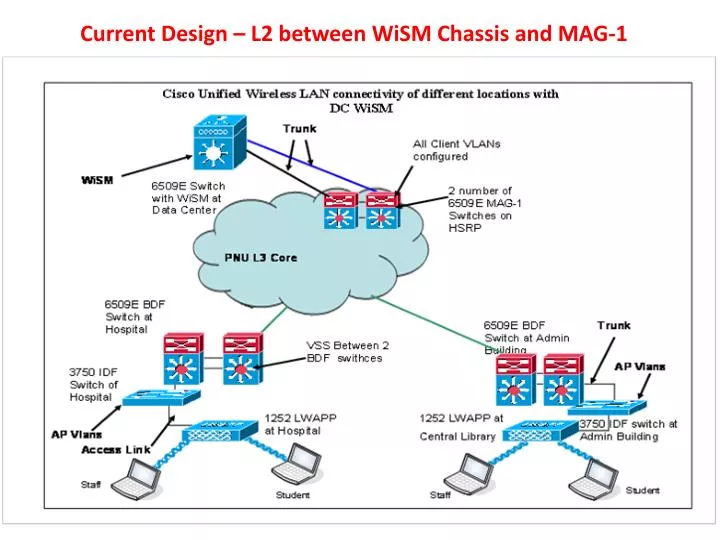
Current Design – L2 between WiSM Chassis and MAG-1. Logical Connectivity. RR . MCD . MAG 1. VLAN 2000. All Active . All Active . All Active . All Active . All Standby. Client VLANS. Client VLANS. Client VLANS. Client VLANS. Client VLANS. 5 x WiSM CHASSIS (including 24 WiSM ).

E N D
Logical Connectivity RR MCD MAG 1 VLAN 2000 All Active All Active All Active All Active All Standby Client VLANS Client VLANS Client VLANS Client VLANS Client VLANS 5 x WiSM CHASSIS (including 24 WiSM)
RR MCD BGP Peering New Design – L3 between WiSM Chassis and MAG-1 BGP Peering MAG 1 VLAN 2000 L3 L3 L3 L3 L3 4 WiSM Active 1 WiSM Standby 4 WiSM Active 1 WiSM Standby 4 WiSM Active 1 WiSM Standby 4 WiSM Active 1 WiSM Standby 3 WiSM Active 1 WiSM Standby WiSM CHASSIS L2 L2 L2 L2 Client VLANS Client VLANS Client VLANS Client VLANS Client VLANS
Each WiSM Chassis will form MP-IBGP Peering with Both RR Each WiSM Chassis will Update MP-IBGP routes to RR based its unique set of VLANs RR Will update the routes to all other BDFs
Routing Plan Each Chassis will have 2 X 10 G etherchannel to MAG 1 MAG 1 Will have VLAN 2000 trunked to Every Chassis Every Chassis will have respective SVI Configured for User VLANs under Respective VRF. Inter Chassis Communication will happen using VLAN 2000 (mobility related etc) For CAPWAP tunnel, each Chassis will originate the respective Host routes of the connected WiSM. Each Chassis Advertises its own Range of IP address into BGP.
CAPWAP Tunnel RR BDF MCD MAG 1 CAPWAP VLAN 2000 WiSM CHASSIS Client VLANS Client VLANS Client VLANS Client VLANS Client VLANS