Download
1 / 45
510 likes | 722 Vues
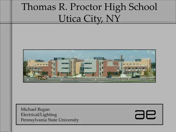
Thomas R. Proctor High School Utica City, NY. Michael Regan Electrical/Lighting Pennsylvania State University. Building Site. Site Plan. 440,000 total square feet Originally built in 1938 as a 7-12 grade school Currently a 9-12 grade school serving nearly 2,000 students

E N D
Thomas R. Proctor High SchoolUtica City, NY Michael Regan Electrical/Lighting Pennsylvania State University
Building Site Site Plan
440,000 total square feet Originally built in 1938 as a 7-12 grade school Currently a 9-12 grade school serving nearly 2,000 students Only high school in its school district Serves as a bridge school for Mohawk Valley Community College Proctor Senior High School Background Information
Analysis • Lighting • Lobby • Library • Auditorium • Structural • Lobby Structural Redesign • Member Sizing Calculations • Results • Electrical • Emergency Data Recovery System • Design Layout and Load Calculations • Equipment Description, Procedure and Layout • Equipment Feeder Sizing • Fault Current Analysis • Equipment Cost • Bus Duct vs. Conduit/Cable • Telecommunications • Telecommunications System Addition • Design Layout • Telecommunications Closets • System Addition Riser Diagram • Lighting • Lobby • Library • Auditorium • Structural • Lobby Structural Redesign • Member Sizing Calculations • Results • Electrical • Emergency Data Recovery System • Design Layout and Load Calculations • Equipment Description, Procedure and Layout • Equipment Feeder Sizing • Fault Current Analysis • Equipment Cost • Bus Duct vs. Conduit/Cable • Telecommunications • Telecommunications System Addition • Design Layout • Telecommunications Closets • System Addition Riser Diagram
Lighting Spaces for Redesign Existing Addition Library Lobby First Floor Plan
2177 square feet Main point of connection to important spaces Extensive use at any time during the day Circulation Space Social Gathering Space Gateway to the library and auditorium during the school day Lighting Design: LobbyBackground Information
Lighting Design: LobbySpatial Layout Library Auditorium Ticket Office
Focus Create an environment that is inviting First space to be seen inside the existing building Be able to provide different appearance schemes Must be able to serve multiple purposes (main hallway during the day, social gathering space in the evening) Criteria Avoid reflected glare Specular floor surface Provide sufficient light to paintings along walls Divert attention to walls rather than specular floor Provide 10-20 fc on floor Provide > 15 fc on paintings Maintain a power density < 1.3W/ft^2 Lighting Design: LobbyDesign Focus and Criteria
Remove and relocate columns from center of lobby Implement 6” 32W wallwash/downlights along perimeter walls and 6” 52W downlights over stairwell Install 4’ 32W strip cove lights along new perimeter shelf of cove • Install dimming controls in ticket booth for perimeter wallwash/downlights and cove lights Lighting Design: LobbyDesign Solutions
Lighting Design: LobbyDesign Solutions 4’ Strip Cove Light Redesigned Section Existing Section
Lighting Design: LobbyDesign Solutions Downlight Wallwash/Downlight Strip Cove Light Luminaire Layout Plan
Lighting Design: LobbyDesign Renderings View of lobby leading to main hallway View of lobby leading to auditorium
Criteria Average illuminance on floor: 10-20 fc Average illuminance on paintings: > 15 fc Power Density < 1.3W/ft^2 Results Average illuminance on floor: 19.18 fc ok Average Illuminance on paintings: 22.78 fc ok Power Density:2340W / 2177ft^2 = 1.07W/ft^2 ok Lighting Design: LobbyDesign Results
Approximately 7,800 sq. ft Adjacent to the lobby Divided into two main areas (book stacks area with circulation desk and reading area) Extensive use during the day Not in use after school hours Lighting Design: LibraryBackground Information
Lighting Design: LibrarySpatial Layout Computer/Reading Area Stacks/Reading/ Circulation Area Entrance/Exit Pathway
Focus Create a bright environment that encourages learning Very task-oriented space Important to maintain light level requirements Establish the stacks area and reading area as two distinct spaces Make means of egress through the large space easily identifiable Criteria Maintain a minimum of 30 fc on horizontal workplane of reading areas Avoid reflected glare in reading spaces assuming that some may have computers Provide uniform illuminance to the top of wall stacks Integrate daylight from window wall to conserve energy during the school day Lighting Design: LibraryDesign Focus and Criteria
Lighting Design: LibraryDesign Solutions • 2x2 recessed luminaires • 6” wallwash/downlights • 6”recessed downlights • Indirect pendants • Two rows of pendants nearest to the windows dimmed via photosensor for energy savings
Lighting Design: LibraryDesign Solutions 2x2 troffers Indirect Pendant Downlight Wallwash/Downlight Luminaire Layout Plan
Lighting Design: LibraryDaylight Dimming Analysis Assumptions Lights on for 8 hours per day To account for typical school days: subtract June 7 to August 25 and multiply total days by 5/7 Conclusions Energy savings/year: $134.33 Payback period: ~17 years (assuming $65 extra for dimming ballast) Recommendation: Dimming system (assuming 50,000 hours of ballast life)
Lighting Design: LibraryDesign Solutions View from main lobby entrance View from reception desk View of tables in reading area
Criteria Average illuminance on workplane > 30 fc Average vertical illuminance on wall book stacks: > 30 fc Power Density < 1.3W/ft^2 Results Average illuminance on workplane: 38.97 fc (computer/reading tables) ok 41.28 fc (book stacks) ok Average vertical illuminance on wall book stacks: 31.60 fc ok Power Density:8050W / 7955ft^2 = 1.01W/ft^2 ok Lighting Design: LibraryDesign Results
Design Reasoning 1,598 electrical interruptions totaling 401,301 hours in Utica and surrounding area in 2004 1996 ice storm = loss of power for 3 weeks in Utica Average of at least one 48 hour period of power loss per year Only high school in its district (9 elementary schools, 2 middle schools) Large volume of school Design Overview School converted into emergency data recovery epicenter in times of crisis for community schools and businesses Usually vacant auxiliary gymnasiums converted into localized data epicenters All clean power panels in entire school also backed Electrical DesignEmergency Data Recovery Center
Surface mounted double duplex receptacle boxes every 14 feet (1 circuit/receptacle) 72 people in Gym 1 and 96 people in Gym 2 Total of 168 people (assuming 600VA/person, 3 people/circuit) 225A main circuit breaker panel dedicated to each gym Electrical DesignDesign Layout – Auxiliary Gymnasiums Receptacle circuiting
Electrical DesignDesign Layout – Auxiliary Gymnasiums New panelboard New Panelboard Auxiliary Gym 1 – First Floor Circuiting Plan and Sample Furniture Arrangement Auxiliary Gym 2 – Ground Floor Circuiting Plan and Sample Furniture Arrangement
Electrical DesignDesign Layout – Classrooms/Offices • All clean power panels backed by emergency power -Many offices, classrooms and other spaces • Can support 450 people (assuming 600VA/person) at 80% of demand load
Electrical DesignDesign Layout – Classrooms/Offices Gym 1 Gym 2 Ground Floor Main areas housing existing clean power panels Emergency areas First Floor Main areas housing existing clean power panels Emergency areas Second Floor Main areas housing existing clean power panels Emergency areas Third Floor Main areas housing existing clean power panels Emergency areas
Total demand load: 420 kVA 228 kVA from switchboard 1 192 kVA from switchboard 2 Switchboard 2 loaded to 75% capacity under new scheme Can support a maximum of 708 incoming personnel Electrical DesignDesign Load Calculations and Results Total Emergency System Demand Load @ .85 power factor: (36.72 + j22.75 kVA) (Gym 1) (48.96 + j30.34 kVA) (Gym 2) + (273.68 + j164.29 kVA) (Classrooms/Offices) 359.36 + j217.38 = 420 kVA
600 kW/750 kVA generator 800A ATS 800A main emergency distribution panel 500kVA UPS system 500 kVA k-13 rated transformer 600A static bypass switch 1200A UPS fed distribution panel Electrical DesignEquipment Description
Electrical DesignEquipment Location Main Electrical Room – Basement Sector K
Design Layout Phone/Data combination boxes every 14 ft. 12 RJ-45 jacks/box 6 data jacks 6 phone jacks Each data/phone jack supplied by CAT-6 cable Telecommunications Closets Located in same rooms as new gymnasium panels Each closet fed with (2) 12 strand multi-mode fiber cables and (1) 6 strand multi-mode fiber cable Telecommunications Addition Design
Lighting Redesign Criteria met Viable design solutions Electrical Design Emergency Data Recovery Center conversion is a feasible design proposal Telecommunications Design Addition to existing telecommunications system is necessary for new emergency design scheme Conclusions
I would like to thank the following: My Family Friends and Classmates Entire AE Faculty/Staff Jim Pfluger and Greenmen-Pedersen, Inc. Jim Regan and Phasor Corporation John Reese and Reese Engineering Acknowledgements
Live loads – classrooms = 150 psf (from ASCE-7-02) Live loads – roof = 30 psf (from ASCE-7-02) Dead loads – floors (8” slab) = 75 psf Dead loads – roof (4” slab) = 40 psf *assumed light-weight concrete = 115 pcf (including wire mesh) Column 1 effective area = 347 sf Column 2,3,4 effective area = 267 sf Structural RedesignParameters
Structural RedesignGirders Equation for Simple Beam – Concentrated Load at Center (LRFD Steel Manual): Δmax = PL^3 / 48EI Girder 1: Δmax = (226k)((264”)^3) / (48)(29,000ksi)(15,000in^4) = .1992” Girder 2,3,4: Δmax = (177k)((264”^3) / (48)(29,000ksi)(12,000in^4) = .1934” Both maximum deflection values are similar to those calculated by SAP 2000 and are well under the allowable limit of L/480=.55.
Structural RedesignResults Column 2,3,4/Girder2,3,4 Column 1/Girder1 Column 1: W10 x 60 Column 2,3,4: W10 x 49 Girder 1: W36 x 230 Girder 2,3,4: W36 x 194
Daylight Conditions March 21 – Clear, Cloudy, Overcast June 21 – Clear, Cloudy, Overcast December 21 – Clear, Cloudy, Overcast Procedure 1. determine the target illuminance level on workplane based on the full electric light * 30-fc was used as the target illuminance for the critical point as per the IES Handbook 2. determine the illuminance level from the undimmed lighting system + daylight 3. determine the full contribution from the dimmed lighting system 4. determine the dimming level using the following equation: % dimmed = target – (undimmed + daylight) dimmed 5. determine the input watts used at each condition Lighting Design: LibraryDaylight Dimming Analysis