Download
1 / 25
451 likes | 1.13k Vues
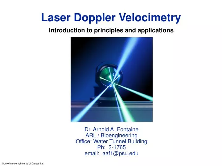
Laser Doppler Velocimetry. Introduction to principles and applications. Dr. Arnold A. Fontaine ARL / Bioengineering Office: Water Tunnel Building Ph: 3-1765 email: aaf1@psu.edu. Some Info compliments of Dantec Inc. Characteristics of LDA. Invented by Yeh and Cummins in 1964

E N D
Laser Doppler Velocimetry Introduction to principles and applications Dr. Arnold A. Fontaine ARL / Bioengineering Office: Water Tunnel Building Ph: 3-1765 email: aaf1@psu.edu Some Info compliments of Dantec Inc.
Characteristics of LDA • Invented by Yeh and Cummins in 1964 • Velocity measurements in Fluid Dynamics (gas, liquid) • Up to 3 velocity components • Non-intrusive measurements (optical technique) • Absolute measurement technique (one calibration required) • Very high accuracy • Very high spatial resolution due to small measurement volume • Tracer particles are required
Applications of LDA • Laminar and turbulent flows • Investigations on aerodynamics • Supersonic flows • Turbines, automotive etc. • Liquid flows • Surface velocity and vibration measurement • Hot environments (flames, plasma etc.) • Velocity of particles • ...etc., etc., etc.
LDA - Optical principle Photodetector • When a particle passes through the intersection volume formed by the two coherent laser beams, the scattered light, received by a detector, has components from both beams. • The components interfere on the surface of the detector. • Due to changes in the difference between the optical path lengths of the two components, this interference produces pulsating light intensity, as the particle moves through the measurement volume. Direction of motion Incident beams Photodetector Direction of motion Incident beams
LDA - Fringe model • Focused laser beams intersect and form the measurement volume • Plane wave fronts: beam waist in the plane of intersection • Interference in the plane of intersection • Pattern of bright and dark stripes/planes
Flow with particles Signal d (known) t (measured) Time • Velocity = distance/time Processor Detector measuring volume Bragg Cell Laser backscattered light
LDA - Fringe model • The fringe model assumes as a way of visualisation that the two intersecting beams form a fringe pattern of high and low intensity. • When the particle traverses this fringe pattern, the scattered light fluctuates in intensity with a frequency equal to the velocity of the particle divided by the fringe spacing.
Transmitting optics Basic modules: • Beam splitter • Achromatic lens Options: • Frequency shift (Bragg cell) • low velocities • flow direction • Beam expanders • reduce measurement volume • increase power density BS Laser Lens Bragg cell D E D DL F
Measurement volume Transmitting system • The transmitting system generates the measurement volume • The measurement volume has a Gaussian intensity distribution in all 3 dimensions • The measurement volume is an ellipsoid • Dimensions/diameters x, y and z are given by the 1/e2intensity points Z DL Y F X Intensity distribution 1 1/e 2 0 z x Z Measurement volume y X Y
Measurement volume Width: Height: Length: z Fringe separation: f 2 sin Z 2 No. of fringes: x f X
Laser, characteristics and requirements • Monochrome • Coherent • Linearly polarised • Low divergence (collimator) • Gaussian intensity distribution Laser L-Diode collimator Laser
Principle of LDA, differential beam technique Flow Transmitting optics Receiving optics with detector Laser HeNe Ar-Ion Nd:Yag Diode Beamsplitter (Freq. Shift) Achrom. Lens Gas Liquid Particle Achrom. Lens Spatial Filter Photomultiplier Photodiode Signal conditioner PC Signal processing Spectrum analyser Correlator Counter, Tracker Amplifier Filter
Sources of noise in the LDA signal: Photo detection shot noise. Secondary electronic noise, thermal noise from preamplifier circuit Higher order laser modes (optical noise). Light scattered from outside the measurement volume, dirt, scratched windows, ambient light, multiple particles, etc. Unwanted reflections (windows, lenses, mirrors, etc). Goal: Select laser power, seeding, optical parameters, etc. to maximise the SNR. Signal characteristics
Directional ambiguity / Frequency shift • Particles moving in either the forward or reverse direction will produce identical signals and frequencies. f fmax fshift fmin u umax umin shift umin umax no shift • With frequency shift in one beam relative to the other, the interference fringes appear to move at the shift frequency. • With frequency shifting, negative velocities can be distinguished.
Frequency shift / Bragg cell • Acousto-optical modulator • Bragg cell requires a signal generator (typically: 40 MHz) • Frequency of laser light is increased by the shift frequency • Beam correction by means of additional prisms fs40 MHz Piezoelectric transducer fL wave front fL + fS Laser Absorber
Detector System configurations Receiving optics with detector Transmitting optics Forward scatter and side scatter (off-axis) • Difficult to align, • Vibration sensitiveBackscatter • Easy to align • User friendly Flow Receiving optics with Detector Transmitting and receiving optics Bragg cell Laser Flow
Seeding: scattered light intensity • Polar plot of scattered light intensity versus scattering angle • The intensity is shown on a logarithmic scale
Seeding: ability to follow flow Following Lumley (1976): Typically: Particle should be small and near neutrally buoyant. d < 50 microns
DATA PROCESSING What is a Signal Processor? System Requirements: Accurate discrimination of burst. High dynamic range. Large frequency range. High data rate capacity. Can discriminate signal in low SNR. Processor Types: Spectrum Analyzers. Photon Correlators. Trackers. Counters. Covariance processor. Digital Signal processor.
DIGITAL SIGNAL PROCESSORS • Digitally sample the burst with a high frequency, accurate A-D and then perform a variety of signal processing techniques to determine the Doppler frequency. • These are the state of the art in processing. • These processors combine: • High pass filters to remove low frequency components such as the signal pedestal and low frequency noise. • Low pass filters to limit high frequency noise components. • High speed A/D converter. • Burst detection algorithms to help identify burst from background signal. Digital signal analyzer to estimate the frequency.
LDV SIGNAL BIAS What is Bias? Examples? Types of bias in LDV signals: 1) Velocity bias. 2) Fringe bias. 3) Gradient bias.
To measure three velocity components requires careful alignment. The simplest method is by using a fine pinhole with an opening just large enough that the focused beam can pass through. Fine adjustment can be made using a power meter behind the pinhole maximising the power of light passing through the pinhole for each beam. Probe volume alignment for 3D velocity measurements
REFERENCES • “The laser Doppler technique,” L.E. Drain, J Wiley and Sons Publishers, 1980. • “Report of the Special Panel on Statistical Particle Bias in Laser Anemometry,” R.V. Edwards, J. Fluids Engineering, Vol 109, pp89-93, 1987.