Download
1 / 21
210 likes | 306 Vues
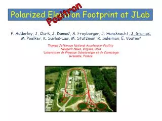
MBE Growth of Graded Structures for Polarized Electron Emitters. Aaron Moy SVT Associates, Eden Prairie, Minnesota. in collaboration with SLAC Polarized Photocathode Research Collaboration (PPRC): T. Maruyama, F. Zhou and A. Brachmann Acknowledgements : US Dept. of Energy SBIR

E N D
MBE Growth of Graded Structures for Polarized Electron Emitters Aaron Moy SVT Associates, Eden Prairie, Minnesota in collaboration with SLAC Polarized Photocathode Research Collaboration (PPRC): T. Maruyama, F. Zhou and A. Brachmann Acknowledgements: US Dept. of Energy SBIR contract #DE-FG02-07ER86329 (Phase I) contract #DE-FG02-07ER86330 (Phase I and II)
Outline • Introduction to Molecular Beam Epitaxy • GaAsP Photocathode • AlGaAsSb Photocathode • AlGaAs/GaAs Internal Gradient Photocathode • Conclusion
Epitaxy Growth of thin film crystalline material where crystallinity is preserved, “single crystal” Atomic Flux Bare (100) III-V surface, such as GaAs Deposition of crystal source material (e.g. Ga, As atoms)
Result: Newly grown thin film, lattice structure maintained Starting surface
Molecular Beam Epitaxy (MBE) • Growth in high vacuum chamber • Ultimate vacuum < 10-10 torr • Pressure during growth < 10-6 torr • Elemental source material • High purity Ga, In, Al, As, P, Sb (99.9999%) • Sources individually evaporated in high temperature cells • In situ monitoring, calibration • Probing of surface structure during growth • Real time feedback of growth rate
Molecular Beam Epitaxy Growth Apparatus:
MBE- In Situ Surface Analysis • Reflection High Energy Electron Diffraction (RHEED) • High energy (5-10 keV) electron beam • Shallow angle of incidence • Beam reconstruction on phosphor screen RHEED image of GaAs (100) surface
H-Plasma Assisted Oxide Removal External view of ignited H-Plasma RHEED image of oxide removal from GaAs Substrate • Regular oxide removal with GaAs occurs at ~ 580 °C • With H-plasma, clean surface observed at only 460 °C
MBE- Summary • Ultra high vacuum, high purity layers • No chemical byproducts created at growth surface • High lateral uniformity (< 1% deviation) • Growth rates 0.1-10 micron/hr • High control of composition and thickness • Lower growth temperatures than MOCVD • In situ monitoring and feedback • Mature production technology
MBE Grown GaN Photocathodes • Unpolarized emission • Very efficient, robust • Can be grown on SiC
MBE Grown GaAsP SL • greater than 1% QE • achieved 86% polarization • material specific spin depolarization mechanism US Dept. of Energy SBIR Phase I and II contract #DE-FG02-01ER83332
Antimony-based SLs for Polarized Electron Emitters • Develop structure based on AlGaAsSb/GaAs material • Sb has 3 orders lower diffusivity than Ga • Sb has higher spin orbit coupling than As
Antimony-based SLs for Polarized Electron Emitters X-ray • Low QE measured for test samples (< 0.2%) • Confinement energy too high --> electrons trapped in quantum wells Band Alignment
Internal Gradient SLs for Polarized Electron Emitters • Photocathode active layers with internal accelerating field • Internal field enhances electron emission for higher QE • Less transport time also reduces depolarization mechanisms • Gradient created by varied alloy composition or dopant profile
Internal Gradient SLs for Polarized Electron Emitters With accelerating field No accelerating field • Order of magnitude decrease in transport time • Increased current density • Projected increase of 5-10% in polarization
Internal Gradient GaAs/AlGaAs SLs for Polarized Electron Emitters 35% to 15% Aluminum grade Non-graded control
Internal Gradient GaAs/AlGaAs SLs for Polarized Electron Emitters X-ray Characterization Simulation Measured Data
Internal Gradient GaAs/AlGaAs SLs • Polarization decreased as aluminum gradient increased • Due to less low LH-HH splitting at low aluminum % • QE increased 25% due to internal gradient field • Peak polarization of 70 % at 740 nm, shorter than 875 nm of GaAs
SBIR Phase II Internal Gradient SLs • Next Steps: • Further graded AlGaAs/GaAs photocathodes • Linear grading versus step grading • Doping gradient • Vary the doping level throughout the active region to generate the accelerating field • Doping gradient applied to GaAsP SL structure
Conclusion • Applying capabilities of MBE to polarized photocathode emitters • AlGaAsSb photocathodes • SBIR Phase II for internal gradient photocathodes • Increase current extraction • Increase polarization