Download

1 / 16
170 likes | 299 Vues
Implement clock divider logic using combinational and sequential logic design. Detailed state table, minimization, and implementation model provided.

E N D
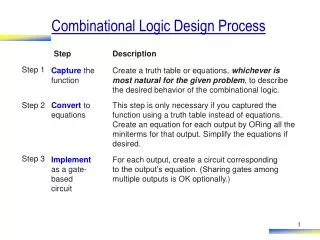
B) Truth table C) Output equations D) Minimized output equations Outputs Inputs y bc y = a'bc + ab'c' + ab'c + abc' + abc a b c y z 00 01 11 10 a 0 0 0 1 0 0 0 0 0 0 0 0 1 0 1 1 1 1 1 1 z = a'b'c + a'bc' + ab'c + abc' + abc 0 1 0 0 1 0 1 1 1 0 y = a + bc z 1 0 0 1 0 bc 00 01 11 10 1 0 1 1 1 a 0 0 1 0 1 1 1 0 1 1 1 1 1 1 1 1 0 1 1 1 E) Logic Gates z = ab + b’c + bc’ a y b c z Combinational logic design A) Problem description y is 1 if a is to 1, or b and c are 1. z is 1 if b or c is to 1, but not both, or if all are 1.
D) State Table (Moore-type) C) Implementation Model B) State Diagram Outputs Inputs Q1 Q0 a I1 I0 x x a Combinational logic 0 0 0 0 0 x=1 x=0 a=0 a=0 0 I1 0 0 1 0 1 0 3 a=1 0 1 0 0 1 I0 0 0 1 1 1 0 a=1 a=1 1 0 0 1 0 0 Q1 Q0 1 0 1 1 1 1 2 1 1 0 1 1 1 a=1 1 1 1 0 0 State register a=0 a=0 x=0 x=0 I0 I1 Sequential logic design • Given this implementation model • Sequential logic design quickly reduces to combinational logic design A) Problem Description You want to construct a clock divider. Slow down your pre-existing clock so that you output a 1 for every four clock cycles
E) Minimized Output Equations F) Combinational Logic Q1Q0 I1 00 01 11 10 a 0 0 1 1 a 0 I1 = Q1’Q0a + Q1a’ + Q1Q0’ x 0 1 0 1 1 Q1Q0 I0 00 01 11 10 a 0 1 1 0 I1 0 I0 = Q0a’ + Q0’a 1 0 0 1 1 x I0 Q1Q0 00 01 11 10 a 0 0 1 0 x = Q1Q0 0 0 0 1 0 Q1 Q0 1 Sequential logic design (cont.)
… … external control inputs external data inputs controller datapath … … registers datapath control inputs next-state and control logic controller datapath datapath control outputs functional units state register … … external control outputs external data outputs … … a view inside the controller and datapath controller and datapath Custom single-purpose processor basic model
!1 1: (a) black-box view 1 !(!go_i) 2: !go_i x_i GCD go_i y_i 2-J: 3: x = x_i d_o 4: y = y_i !(x!=y) 5: x!=y 6: x<y !(x<y) y = y -x x = x - y 7: 8: 6-J: 5-J: d_o = x 9: 1-J: Example: greatest common divisor • First create algorithm • Convert algorithm to “complex” state machine • Known as FSMD: finite-state machine with datapath • Can use templates to perform such conversion (c) state diagram (b) desired functionality 0: int x, y; 1: while (1) { 2: while (!go_i); 3: x = x_i; 4: y = y_i; 5: while (x != y) { 6: if (x < y) 7: y = y - x; else 8: x = x - y; } 9: d_o = x; }
!1 1: 1 !(!go_i) 2: x_i y_i !go_i Datapath 2-J: x_sel n-bit 2x1 n-bit 2x1 3: x = x_i y_sel x_ld 0: x 0: y 4: y = y_i y_ld !(x!=y) 5: != < subtractor subtractor x!=y 5: x!=y 5: x!=y 6: x<y 8: x-y 7: y-x 6: x_neq_y x<y !(x<y) x_lt_y 9: d y = y -x x = x - y 7: 8: d_ld d_o 6-J: 5-J: d_o = x 9: 1-J: Creating the datapath • Create a register for any declared variable • Create a functional unit for each arithmetic operation • Connect the ports, registers and functional units • Based on reads and writes • Use multiplexors for multiple sources • Create unique identifier • for each datapath component control input and output
!1 go_i 1: Controller !1 1 !(!go_i) 1: 0000 2: 1 !(!go_i) 0001 2: x_i y_i !go_i !go_i Datapath 2-J: 0010 2-J: x_sel n-bit 2x1 n-bit 2x1 3: x = x_i x_sel = 0 x_ld = 1 0011 3: y_sel x_ld 0: x 0: y 4: y = y_i y_sel = 0 y_ld = 1 y_ld 0100 4: !(x!=y) 5: !x_neq_y 0101 5: != < subtractor subtractor x!=y x_neq_y 5: x!=y 5: x!=y 6: x<y 8: x-y 7: y-x 6: 0110 6: x_neq_y x<y !(x<y) x_lt_y !x_lt_y x_lt_y 9: d y = y -x x = x - y y_sel = 1 y_ld = 1 x_sel = 1 x_ld = 1 7: 8: 7: 8: d_ld 0111 1000 d_o 6-J: 1001 6-J: 5-J: 1010 5-J: d_o = x 9: d_ld = 1 1011 9: 1-J: 1100 1-J: Creating the controller’s FSM • Same structure as FSMD • Replace complex actions/conditions with datapath configurations
x_i y_i (b) Datapath x_sel n-bit 2x1 n-bit 2x1 y_sel x_ld 0: x 0: y y_ld != < subtractor subtractor Controller implementation model 5: x!=y 5: x!=y 6: x<y 8: x-y 7: y-x go_i x_neq_y x_sel Combinational logic y_sel x_lt_y 9: d x_ld d_ld y_ld d_o x_neq_y x_lt_y d_ld Q3 Q2 Q1 Q0 State register I3 I2 I1 I0 Splitting into a controller and datapath go_i Controller !1 1: 0000 1 !(!go_i) 0001 2: !go_i 0010 2-J: x_sel = 0 x_ld = 1 0011 3: y_sel = 0 y_ld = 1 0100 4: x_neq_y=0 0101 5: x_neq_y=1 0110 6: x_lt_y=1 x_lt_y=0 y_sel = 1 y_ld = 1 x_sel = 1 x_ld = 1 7: 8: 0111 1000 1001 6-J: 1010 5-J: d_ld = 1 1011 9: 1100 1-J:
Inputs Outputs Q3 Q2 Q1 Q0 x_neq_y x_lt_y go_i I3 I2 I1 I0 x_sel y_sel x_ld y_ld d_ld 0 0 0 0 * * * 0 0 0 1 X X 0 0 0 0 0 0 1 * * 0 0 0 1 0 X X 0 0 0 0 0 0 1 * * 1 0 0 1 1 X X 0 0 0 0 0 1 0 * * * 0 0 0 1 X X 0 0 0 0 0 1 1 * * * 0 1 0 0 0 X 1 0 0 0 1 0 0 * * * 0 1 0 1 X 0 0 1 0 0 1 0 1 0 * * 1 0 1 1 X X 0 0 0 0 1 0 1 1 * * 0 1 1 0 X X 0 0 0 0 1 1 0 * 0 * 1 0 0 0 X X 0 0 0 0 1 1 0 * 1 * 0 1 1 1 X X 0 0 0 0 1 1 1 * * * 1 0 0 1 X 1 0 1 0 1 0 0 0 * * * 1 0 0 1 1 X 1 0 0 1 0 0 1 * * * 1 0 1 0 X X 0 0 0 1 0 1 0 * * * 0 1 0 1 X X 0 0 0 1 0 1 1 * * * 1 1 0 0 X X 0 0 1 1 1 0 0 * * * 0 0 0 0 X X 0 0 0 1 1 0 1 * * * 0 0 0 0 X X 0 0 0 1 1 1 0 * * * 0 0 0 0 X X 0 0 0 1 1 1 1 * * * 0 0 0 0 X X 0 0 0 Controller state table for the GCD example
… … controller datapath registers next-state and control logic functional units state register … … a view inside the controller and datapath Completing the GCD custom single-purpose processor design • We finished the datapath • We have a state table for the next state and control logic • All that’s left is combinational logic design • This is not an optimized design, but we see the basic steps
Example • Consider the following algorithm that gives the maximum of two numbers. 0: int x, y, z; 1: while (1) { 2: while (!start); 3: x = A; 4: y = B; 5: if (x >= y) 6: z = x; else 7: z = y; }
Example – Cont. • Now, consider the following VHDL code that gives the maximum of two numbers. ----------------------------------------------------------------------------------------- entity MAX is generic(size: integer:=4); port( clk, reset, start: in std_logic; x_i, y_i :in std_logic_vector(size-1 downto 0); z_o: out std_logic_vector(size-1 downto 0)); end MAX; architecture behavioral of MAX is type STATE_TYPE is (S0, S1, S2, S3, S4); signal Current_State, Next_State: STATE_TYPE; signal x, y, mux : std_logic_vector (size-1 downto 0):= (others => '0'); signal z_sel, x_ld, y_ld, z_ld : std_logic := '0'; begin
----------------------------------------------- Reg_x: process (CLK) begin if (CLK'event and CLK='1') then if reset='1' then x <= (others => '0'); else if (x_ld='1') then x <= x_i; end if; end if; end if; end process; ----------------------------------------------- Reg_y: process (CLK) begin if (CLK'event and CLK='1') then if reset='1' then y <= (others => '0'); else if (y_ld='1') then y <= y_i; end if; end if; end if; end process; ----------------------------------------------- ----------------------------------------------- Reg_z_o:process (CLK) begin if (CLK'event and CLK='1') then if reset='1' then z_o <= (others => '0'); else if (z_ld='1') then z_o <= mux; end if; end if; end if; end process; ----------------------------------------------- Multiplexer: process (x, y, z_sel) begin if (z_sel='0') then mux <= x; elsif (z_sel='1') then mux <= y; end if; end process; ----------------------------------------------- Example – Cont.
----------------------------------------------- SYNC_PROC: process (CLK, RESET) begin if (RESET='1') then Current_State <= S0; elsif (CLK'event and CLK = '1') then Current_State <= Next_State; end if; end process; ----------------------------------------------- ----------------------------------------------- COMB_PROC: process (Current_State, start, x, y, z_sel) begin case Current_State is -------------------------- when S0 => -- idle if (start='1') then Next_State <= S1; else Next_State <= S0; end if; -------------------------- when S1 => -- x = x_i & y = y_i x_ld <= '1'; y_ld <= '1'; z_ld <= '0' Next_State <= S2; -------------------------- when S2 => -- x ≥ y x_ld <= '0'; y_ld <= '0'; if (x >= y ) then Next_State <= S3; else Next_State <= S4; end if; -------------------------- when S3 => -- z = x z_sel <= '0'; z_ld<=’1’; Next_State <= S0; -------------------------- when S4 => -- z = y z_sel <= '1'; z_ld<=’1’; Next_State <= S0; end case; end process; ---------------------------------------------- Example – Cont.