Download
1 / 37
430 likes | 808 Vues
IMAGE PROCESSING USING FPGA. Sumitha Ajith Saicharan Bandarupalli Mahesh Borgaonkar. Project Phases. In Simulation Stage Development of an Algorithm for Blob Detection What is blob detection Sequential Connected Component Algorithm Our optimized Implementation Simulation results

E N D
IMAGE PROCESSINGUSING FPGA Sumitha Ajith Saicharan Bandarupalli Mahesh Borgaonkar
Project Phases • In Simulation Stage Development of an Algorithm for Blob Detection • What is blob detection • Sequential Connected Component Algorithm • Our optimized Implementation • Simulation results • Main Part Hardware implementation • VGA display using Block RAM as Video Memory • VGA display using SRAM as Video Memory
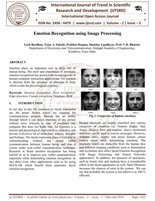
What is Blob Detection? • Identify connected Pixels [Blob] • Identify blob by color • Measure Blob Parameters • Area • Centroid
Considerations Challenges • Algorithms typically sequential with multiple stages • Makes Real-Time Image Processing Hard • Large Storage Demands • Source. • Processed Image. • Intermediate Images. • Memory Access Latency and Contention Algorithm Focus • Minimize Storage Requirements • Minimize Number of Passes (Stages) for Processing Processing Block Imagesource Display Module On Board SRAM Chips Memory Heavily Strained Optimize to reduce Scheduling Issues
Labeling • Uses Sequential Connected Component Algorithm Psuedo-code
Labeling - Example Source Image Intermediate Labeled Image BLOB Detected!
Blob Parameters • Calculations:
Optimized Labeling • Implementation: • Usage of LINE FIFO to get North Labels • Blob Parameter Table Design and Update Logic • Facilitates Single Pass Blob Parameter Calculation Image source Pixel by pixel Label the Pixel Update Blob Parameter Table SRAM Blob detection Module
Blob Table Update • MergeTable[MergeLabel] = Merge Table[PresentLabel] • Running Counters : Area , XBar, Ybar • Incremented during each hit to a valid pixel • Check if you merged two labels. If so increment only one counter. Index By Blob Label Merge Label Update Table Threshold LABEL Update Counters Memory Image source Process Complete Centroid Calculator Table look up DIVIDER Table Update
Results • Blob detection done on the way from Image source to Memory. • Modelsim Simulation Results
Hardware and Software used • Synthesis • Xilinx ISE • Downloading bit File • Impact • Spartan 3 FPGA Board [costs $ 140]
Part 1: VGA display Interface with Block RAM as Video MemoryPart 2:VGA display Interface with SRAMas Video Memory
Part 1 : Synch Signals Generator & Block Memory • VGA module generate the five active signals : hsync, vsync & three video signals Red, Green and Blue • Block RAM is special memory module embedded in FPGA device separated from regular logic cells. • Xilinx Core Gen Feature is used to generate blockRAM. • Each block RAM consist of a 16k by 1 to 512 by 32. • A 24 bit sample picture is taken and converted into a 3 bit format which can be initialized in Block RAM • Xilinx BlockRAM can be initialized with the .coe file.
Test Results : Sync Signal Generator • VGA Synch Signal generator Test Results: Screen bitmapped to unique color input read from Switches
S3 board has a megabyte of fast asynchronous SRAM, surface mounted. • It has two 256K*16 SRAM devices. • Both devices shares common write-enable, output-enable and address signals. • But each has a separate chip select. S3 FPGA Memory
Role of Memory Controller • The S3 board has two 256k-by 16 synchronous SRAM devices, which total 1MB. • A memory controller has been constructed for these devices. • The timing characteristics of each RAM device are different, controller is applicable to only one particular device. • Memory controller is used as interface, between main system and SRAM. • The performance of memory controller is measured by number of memory access that can be completed I given time.
When the main system wants to access memory, it places address and data on the bus and activates the command. • At raising edge of clock, all signals are sampled by memory controller and desired operation is performed.
SRAM Read and Write Timing • Read cycle • The we_n, write enable should be deactivated. • Place the address on address bus and activate the oe_n signal. • Wait for address access time (taa), as data from SRAM becomes available. • Retrieve the data and deactivate the oe_n signal.
Write cycle • Place the address on the bus and data on dio bus and activate the we_n signal. • Wait for we_n pulse width and then deactivate we_n signal. The data is latched to SRAM at raising edge. • Remove the data from bus.
Additional Considerations • Should be fast enough to feed the VGA controller whose pixel rate is 25MHz • Board clock is only 50MHz • SRAM has access latency of only 10ns. • Possible to come up with a FSM whose Read and write cycles are small but with a fast clock.
Digital Clock Manager from Xilinx • Use Xilinx DCM feature to increase clock frequency. • Board Clock 50MHz • Output : 200 MHZ
Memory Controller FSM : @200MHZ • The FSM consist of Idle stat • Read and write. • Back to Back read operations will take 20 ns to complete. • Same timing constraints for write. • Each block i.e. Idle, read 1, read 2, read 3 requires 5 ns, so the total time is 20ns.
Sequence of Events • Image is initialized in the Block RAM • Wait for user input : BTN Press. • On BTN press – Image is transferred from BRAM to SRAM • Simultaneously Image gets displayed on the screen • FSM is designed to sequence theses events
Transferring Image from BRAM to SRAM Runs @ 200MHz Button Press
Demo VGA DISPLAY FROM SRAM
Future Work • Camera Interfacing: • Synthesize Blob Detection Algorithm • Design a Memory Scheduler to synchronize events • Implement Object Tracking
Conclusion Learning Experience • Synthesizable Verilog Programming for FPGA • Use Xilinx inbuilt features such as DCM, Block RAM • Building a SRAM Memory controller • How multiple FSMs work together. • Concept of VGA displays. • Image Processing Fundamentals Review