Download
1 / 45
480 likes | 794 Vues
GNSS SIMULATION FUNDAMENTALS. Paul G Crampton March 2012. System Components. Typically PC, Signal Generator and Unit Under Test. System Components (2). For some simulators the PC is not necessary. System Components (3). Software.

E N D
GNSS SIMULATION FUNDAMENTALS Paul G Crampton March 2012
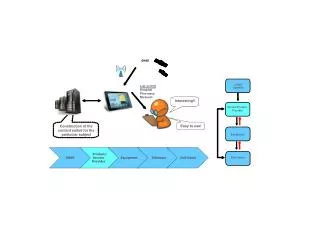
System Components • Typically PC, Signal Generator and Unit Under Test
System Components (2) • For some simulators the PC is not necessary
Software • Variety of Software Packages depending on the simulator and it’s capabilities • SimCHAN • SimREPLAY • SimREPLAYPlus • SimINERTIAL • SimGEN
SimGEN for Windows • SimGEN is a the primary interface software for Spirent’s broad range of Satellite Navigation Simulators • SimGEN also provides the control of the simulator hardware via a proprietary interface over USB for GSS6700 simulators and TCP/IP for GSS8000 simulators (IEEE488 for older GSS7700 and STR4760 units – STR4500 and GSS6560 were also USB) • Through the user interface or remotely, SimGEN enables the specification, development and execution of simulations • The simulations are saved as Scenarios, which are constructed of a set of source files for customizing and manipulating various settings in the simulation
Starting SimGEN • SimGEN is preinstalled on all SimGEN PCs • Starting SimGEN can be performed by either: • Desktop Icon • Start Menu • Note: Also in the Start Menu under SimGEN are various applications and documents
Starting SimGEN (cont.) • Starting SimGEN begins with the view to the right • This window allows the user to select the desired scenario to use for the simulation • By default, the scenario shown after starting SimGEN is the last successful scenario used
SimGEN Main Window • The overview of the SimGEN Main Window and its features is shown below Toolbar Menu Vehicle Dials Date and Time Power Levels Ground Track Scenario ContentsWindow Skyplot MessageWindow Status Bar
Scenario Contents Window • The scenario contents window contains all of the scenario source files (i.e. detailed features) for the simulation • For instance: • Various input/output data options • Atmosphere models • Desired constellation (GPS, GLONASS, ephemeris, etc.) • Vehicle information • Vehicle Trajectory • Aiding data • Antenna patterns, lever arms and boresight
Selecting and Opening Scenarios • Similar to other Windows applications, scenarios are opened under File > Open as shown below • Going “Up one level” the user can select other scenarios as shown
Scenario File Hierarchy • Systems are normally shipped with the example scenarios under the default location: • C:\Program Files\Spirent Communications\SimGEN\Scenarios • Each scenario is stored in its own folder (taking the same name as the scenario) under a common parent folder • Scenarios under a common parent folder may share common files from a folder named “shared” Shared Folder for shared files User Generated Scenarios Pre-installed scenarios
Run Button Starting a Scenario • To start a scenario, press the run button on the tool bar • The scenario will then start on the next internal 1PPS (if set to internal trigger) • After the scenario has started, the Status bar will then update with a Running indicator that will start to flash to show that the scenario is running
Stopping a Scenario • There are several ways to stop a scenario • By default, the Scenario will automatically stop when the predefined scenario duration has been reached • It can also be stopped prior to the duration end manually with the halt button on the tool bar • After stopping a scenario, the user will be prompted to rewind the scenario and save any selected files Halt Button
Connecting a Receiver • There are 2 ways of transferring the signal from the simulator to the receiver • Direct coaxial connection • Radiation in a controlled environment - Be Careful! • The simulator output is presented as an open-circuit 50 transmission line via an N-type (or SMA) connector
Scenario Components • At its most basic a “Scenario” comprises a few key elements of the simulation:
Scenario Components • With the antenna characteristics
Websites for GPS, GLONASS & Galileo Almanacs • http://www.navcen.uscg.gov/gps/almanacs.htm • http://www.glonass-ianc.rsa.ru • Galileo :
Once we have the Vehicle Location… • …We can determine which satellites should be visible
Satellite Characteristics • Position and Motion • Rising and Setting • Pseudorange and Carrier Phase • Signal Levels • Frequencies and Codes • Services (Galileo) • Navigation Data • Clock Performance
Atmospheric Effects • Tropospheric and Ionospheric Effects are typically modeled within the receiver • If the simulator doesn’t take these effects into consideration then receiver position error will reflect the atmospheric delays.
Adjusting Satellite Signal Power • It is often useful to have control of the satellite signal power during simulation testing • For instance this provides the benefit of: • Configuring all of the satellites for a nominal transmission power level • Compensation for signal loss from couplers or transmission lines • Providing the desired carrier-to-noise (C/No) at the receiver • Sensitivity testing for determining when the receiver can acquire or track satellites at various power levels
Adjusting Satellite Signal Power (cont.) • The Signal Power menu shown to the right allows the user to define power offsets for each signal, code and satellite • The Global Offset is used for specifying the reference power level for each satellite • Useful for instance for modifying the signal power to obtain the desired C/No at the receiver • Can easily be applied to satellites using the All button
Adjusting Satellite Signal Power (cont.) • Signal power levels can also be adjusted in real-time in SimGEN • This is useful for reacquisition testing or if the C/No is observed to be too low by the receiver after the test has started for instance • Accessing this for each satellite can be performed by: • Double-clicking the Signal Powers menu or.. • Using the shortcut on the Toolbar • Adjusting the sliders adjusts the signal power for each satellite • Satellites can be turned “off” by checking Signal Off • If All channels selected then whatever is performed to one satellite is performed to all
Conclusion • Hopefully this presentation discussed just the fundamentals of simulation • Subsequent presentations will build on this framework
Thank You Paul G Crampton