Download
1 / 9
0 likes | 21 Vues
Step-by-step methods for designing and validating TEMA S-Class heat exchangers. Get expert tips and insights!

E N D
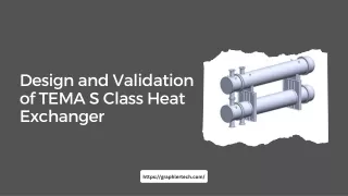
Design and Validation of TEMA S Class Heat Exchanger https://graphlertech.com/
PROJECT INFO • Our client is a leading manufacturer and supplier of Shell & Tube, Plate type Heat exchangers, Boilers and Pressure vessels. • The client’s requirement is to design ’Floating Head Heat Exchanger’ in compliance with ASME Sec VIII and TEMA class S specifications.
PROJECT INFO • We at Graphler Tech was appointed to design detailed 3D model, prepare General arrangement, Fabrication drawings and to issue detailed drawings for various components in the Heat exchanger.
WHAT WE DELIVERED • 3D CAD Model as per Client’s requirement/specifications • General Arrangement Drawings • Fabrication drawings • Machine drawings of various components • Parts drawings of various components • Detailed Bill of materials • CFD simulations to ensure customer’s design criteria is met • FE simulations to ensure structural integrity during lifting, transportation.
DESIGN SPECIFICATIONS • The Floating Head Heat Exchanger is designed for: • Pressure rating: Shell side: 38 kg/sq. cm, and Tube side: 30 kg/sq. cm • Temperature rating: Shell side: 150 °C and Tube side: 110 °C • Fluid capacity, Shell side: 2.8 cu.m., and Tube side: 1.8 cu.m • No. of passes: shell side (cross flow) and tube side (10).
DESIGN SPECIFICATIONS • Design wind reluctance: 50 m/s as per IS 875 Part 3 • Seismic design code: IS: 1893-2005 • Insulation thickness is 15/50 mm. • Gross weight of Heat exchanger (empty): 13 tons • Through simulations, we were able to provide nozzle loads, wind seismic data, bolt torque and forces, and welding stresses and forces. • Detailed drawings were provided to Davit for cover, insulation clatters, tube bundles with tube-to-tube sheet joints, tube layouts, baffle layouts, tie rods, girth flanges, passage partitions, gaskets, hold points, name plates, etc. • Finally, all design information, like native 3D CAD data, drawings and simulation reports, was submitted to the customer.
DESIGN • You can come up with new routes by teaming up with a leading Stress Analysis Services Partner or Product Design Companies with a good reputation.
CFD ANALYSIS VALIDATION • CFD simulations were performed to understand the velocity and temperature distribution on Shell and tube side. The heat exchanger was simulated with operating temperature and pressure. • The best way to obtain the accurate information is to consult an experienced CFD Consulting Services or Structural Analysis Services provider.