Download

1 / 9
0 likes | 28 Vues
Shree Trading Syndicate is The House Of Capacitors, Supplier, Dealer And Authorised Distributors Of Epcos Power Capacitor, CV Capacitors, Epcos Round Capacitor, Epcos Square Capacitor, Epcos Oil Filled Capacitor, Epcos Gas Filled Capacitor, Mumbai, India

E N D
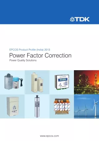
EPCOS Product Profile (India) 2013 Power Factor Correction Power Quality Solutions www.epcos.com
Preview I U U I Linear loads: Non linear load produce non sinusoidal currents when voltage was followed by current. connected to sinusoidal voltage. General How reactive power is generated The increasing demand of electrical Every electric load that works with reactive power compensation systems power and the awareness of the magnetic fields (motors, chokes, (detuned/conventional) are installed necessity of energy saving is very up transformers, inductive heating, arc for larger loads like industrial machinery. to date these days. Also the aware- welding, generators) produces a vary- Such systems consist of a group ness of power quality is increasing, ing degree of electrical lag, which is of capacitor units that can be cut in and power factor correction (PFC) and called inductance. This lag of inductive and cut out and which are driven and harmonic filtering will be implemented loads maintains the current sense (e.g. switched by a power factor controller. on a growing scale. Enhancing power positive) for a time even though the quality – improvement of power factor negative-going voltage tries to reverse * – saves costs and ensures a fast it. This phase shift between current sin * return on investment. In power distrib- and voltage is maintained, current and With power factor correction the apparent power ution, in low- and medium-voltage voltage having opposite signs. During S can be decreased by reducing the reactive power Q. networks, PFC focuses on the power this time, negative power or energy flow (cos Ø) and the optimization of is produced and fed back into the voltage stability by generating reactive network. When current and voltage Reactive Power [KVAr] 2 2 2 power – to im prove voltage quality and have the same sign again, the same Q = S — P reliability at distribution level. amount of energy is again needed to Q Q 2 C build up the magnetic fields in induc- Q1 tive loads. This magnetic reversal energy is called reactive power. S2 P j 1 In AC networks (50/60 Hz) such a S1 j process is repeated 50 or 60 times a 2 second. So an obvious solution is to Apparent Power [kVA] 2 2 2 S = P + Q briefly store the magnetic reversal energy in capacitors and relieve the Active Power [kW] 2 2 2 P = S — Q network (supply line) of this reactive energy. For this reason, automatic Power factor Power factor improvement Types of PFC (detuned or conventional) results in Power factor improvement can be achieved by individual or fixed compensation Higher energy consumption and (each reactive power producer is costs, Compensation of reactive power individually compensated), Less power distributed via the with capacitors, group compensation (reactive power network, Active compensation – using producers connected as a group Power loss in the network, semiconductors, and compensated as a whole), Higher transformer losses, Overexcited synchronous machine central or automatic compen sation Increased voltage drop in power (motor/generator). (by a PFC system at a central point), distribution networks. mixed compensation. 4 EIPL 2013
Preview Power Quality Solution strategy Application know-how tests under laboratory conditions that Along with the emerging demand for Technical skills may differ significantly from the reality power quality and a growing aware- Extensive experience in the field of in the field. In addition, load structures ness of the need for environmental power quality improvement have changed from being mainly linear protection, the complexity in the ener- A worldwide network of partners in the past to non-linear today. All this energy market is increasing: users and Continuous development produces a clear trend: the market decision-makers are consequently Sharing of information is calling increasingly for customized finding it increasingly difficult to locate the best product on the market and to solutions rather than off-the-shelf These are the cornerstones on which make objective decisions. It is in most products. This is where Power Quality Power Quality Solutions are built. On cases not fruitful to compare catalogs Solutions come into the picture. It the basis of this strategy, EPCOS is and data sheets, as many of their offers all key components for an not only the leading manufacturer of parameters are identical in line with effective PFC system from a single power capacitors for PFC applications the relevant standards. Thus operating source, together with: but also a PQS supplier with a century times are specified on the basis of of field experience, reputation and reliability. Uninterruptible Power supply Power Factor Correction (PFC) and Harmonic Filtering EMC filter C DC link Linear load Dynamic Passive Active Tuned (Aluminum electrolytic with fixed PFC harmonic harmonic harmonic or film capacitors) PFC systems filters filters filters Frequency converter Overvoltage Overvoltage Overvoltage Overvoltage Overvoltage protection protection protection protection protection Charging resistor M 3~ C (de-tuned M 250/350/ PFC EMC filter Output filter 3~ systems) 550 Hz EIPL 2013 5
PQS Key Components Overview PF controllers BR6000 BR6000-R06 BR6000-R12 BR6000-T06 BR6000-T12 Supply voltage 245 V AC( 20%; L-N) 245 V AC ( 20%; L-N) 245 V AC ( 20%; L-N) 245V AC ( 20%; L-N) Measurement 30-525 V AC (L-N) 30-525 V AC (L-N) 30-300 V AC (L-N) 30-300 V AC (L-N) voltage range or (L-L) or (L-L) - - Measurement X/5 or X1/A X/5 or X1/A X/5 or X1/A X/5 or X1/A current selectable selectable selectable selectable Frequency 50/60 Hz 50/60 Hz 50/60 Hz 50/60 Hz BR5000 BR5000-R08 BR5000-R16 BR5000-T16 Supply voltage 415V AC 415V AC 415V AC (-40% to +20%; L-L) (-40% to +20%; L-L) (-40% to +20%; L-L) Measurement 3Ph 3wire 415V AC 3Ph 3wire 415V AC 3Ph 3wire 415V AC voltage range (-40% to +20%) (-40% to +20%) (-40% to +20%) Measurement current X/5 or X1/A selectable X/5 or X1/A selectable Only 5Amp CT secondary Frequency 45Hz to 62.5Hz 45Hz to 62.5Hz 45 Hz to 55 Hz BR4000 BR 4904 BR 4008 Supply voltage 230V AC (-25% to +20%; L-N) 230V AC (-25% to +20%; L-N) Measurement voltage range 230V AC (-25% to +20%; L-N) 230V AC (-25% to +20%; L-N) Measurement current X/5 or X1/A externally selectable X/5 or X1/A externally selectable Frequency 47Hz to 53 Hz 47Hz to 53 Hz BR Series and Ordering Details Output stages Relay outputs Transistor outputs Interface Ordering code BR6000-R06 6 - B44066R6006R230N 1 BR6000-R12 12 - B44066R6012R230N 1 BR6000-R12 12 - RS232 B44066R6312R230N 1 BR6000-R12 12 - RS485 B44066R6412R230N 1 BR6000-T06 - 6 - B44066R6106R230N 1 BR6000-T12 - 12 - B44066R6112R230N 1 BR5000-R08 8 - RS232 and RS485 B44066R5908A415N 1 BR5000-R16 16 - RS232 and RS485 B44066R5916A415N 1 BR5000-T16 - 16 RS232 and RS485 B44066R5716A415N 1 BR4904 4 - - B44066R4904A230N 1 BR4008 8 - - B44066R4808A230N 1 BR7000 15 relay outputs PF controller for 3 phase measuring and controlling B44066R7415E230 MC7000-3 Grid analysis tool for 3 phase measuring, display and storage B44066M1301E230 of electric parameters 8 8 EIPL 2013
Important Notes The following applies to all products named in this 4. In or der to satisfy certain technical requirements, some of publication: the products described in this publication may contain substances subject to restrictions in certain jurisdictions 1. Some parts of this publication contain s tatements about (e.g. because they are classed as hazardous). the suitability of our products for certain areas of appli- Useful information on this will be found in our Material cation. These statements are based on our knowledge Data Sheets on the Internet (www.epcos.com/material). of typical requirements that are often placed on our prod- Should you have any more detailed questions, please ucts in the areas of application concerned. We neverthe- contact our sales offices. less expressly point out that such statements cannot be regarded as binding statements about the suitability 5. We constantly strive to improve our products. Conse- of our products for a particular customer application. quently, the products described in this publication As a rule, EPCOS is either unfamiliar with individual may change from time to time. The same is true of the customer applications or less familiar with them than corresponding product specifications. Please check the customers themselves. For these reasons, it is always therefore to what extent product descriptions and speci- ultimately incumbent on the customer to check and decide fications contained in this publication are still applicable whether an EPCOS product with the properties described before or when you place an order. in the product specification is suitable for use in a partic- We also reserve the right to discontinue production ular customer application. and delivery of products.Consequently, we cannot 2. We also point out that in individual cases, a malfunc- guarantee that all products named in this publication will tion of electronic components or failure before the always be available. end of their usual service life cannot be completely The aforementioned does not apply in the case of ruled out in the current state of the art, even if they are individual agreements deviating from the foregoing for operated as speci fied . In customer applications requiring customer-specific products. a very high level of operational safety and especially in 6. Unless otherwise agreed in individual contracts, all customer applications in which the malfunction or failure orders are subject to the current version of the “General of an electroniccomponent could endanger human life or Terms of Delivery for Products and Services in health (e.g. in accident prevention or life-saving systems), the Electrical Industry” published by the German it must therefore be ensured by means of suitable design Electrical and Electronics Industry Association (ZVEI). of the customer application or other action taken by the customer (e.g. installation of protective circuitry or 7.The trade names EPCOS, BAOKE, Alu-X, CeraDiode, redundancy) that no injury or damage is sustained by third CSMP , CSSP , CTVS, DeltaCap, DigiSiMic, DSSP , parties in the event of malfunction or failure of an electronic SquareCap, FormFit, MiniBlue, MiniCell, MKD,MKK, component. AgriCap, PoleCap, MLSC, MotorCap, PCC, PhaseCap, PhaseCube, PhaseMod, PhiCap, SIFERRIT, SIFI, 3. The warnings, cautions and product-specific notes must be observed. SIKOREL, SilverCap, SIMDAD,SiMic,SIMID,SineFormer, SIOV, SIP5D, SIP5K, ThermoFuse, WindCap are trademarks registered or pending in Europe and in other countries. Further information will be found on the Internet at www.epcos.com/trademarks. 10 EIPL 2013
PF Controllers BR4000 Series Intelligent l l User-friendly Cost-effective General The BR4000 controller series is BR4000 Controller series is the most economical series and available in 4 stages and 8 stages. Best suited with conventional intended to serve the basic APFC applications. purpose of power factor corrections... The simplest menu driven version controller with navigational keys. The microcontroller based logic, multifunctional display of electrical parameters, compact size 96 x 96 mm and protections makes this controller extremely user friendly. Features Protection Warning Technical Data Microcontroller logic for Over / under voltage Measurement voltage: Over / under load measurements 1PH 230 VAC Over temperature User friendly operation (-25% to +20%) User friendly operation Control mode: binary, unequal, Current input selectable - 1A or 5A for load with Preset and User defined Important display parameters Multifunctional LCD display class 2 accuracy Voltage Single CT sensing for unbalanced Auxiliary supply - 1Ph, 230V Current (-25% to +20%) loads Active power Steps - 4 and 8 relay Compact 96X96 mm front fascia Reactive power Suitable for auto / manual outputs Apparent power Supply frequency operation Frequency -47 Hz to 53 Hz Individual harmonic measurement th VTHD upto 15 ITHD Mechanical and Maintenance Compact size Operating temperature O O - 0 to 50 C Storage temperature - O O -5 C to 65 C Humidity -0 to 98% EIPL 2013 45
PF Controllers BR4000 Series Intelligent l l User-friendly Cost-effective Typical wiring diagram for PF correction Load side Aux and Load Capacitor Bank Meas Current Voltage CT L1 (R) L2 (Y) L3 (B) N PE 2A 6A L1 N S S1/S5 COM K1 BR 4008 Controller C1C2C3C4 C8 Rear side terminals - measurement voltage, measurement current and auxiliary supply Auxiliary and Measurement Load CT Connection Voltage Connection Selectable 1A or 5A 230 V, 1 Phase, 2 Wire Example: Select either S1 (1A) or S5 (5A) along with S (common) L1 S1 S5 N S COM C8 C7 C6 C5 C4 C3 C2 C1 Output commands to capacitor contactors 46 EIPL 2013
PF Controllers BR4000 Series Intelligent l l User-friendly Cost-effective Selection table for controllers BR4000 relay output Steps 4 STEP 8 STEP Switching Contactor Contactor Ordering code B44066R4904A230N1 B44066R4808A230N1 Auxiliary supply / 1-Phase, 2-Wire, 230 Vac (-25% to +20%) 1-Phase, 2-Wire, 230 Vac (-25% to +20%) Measurement voltage (common for both measurement and auxiliary) (common for both measurement and auxiliary) Load CT input current 1 / 5 A - separate connectors for 1 / 5 A - separate connectors for either of the CT connections either of the CT connections No. of outputs 4 Nos. Relay o/ps of 5A @230V AC Resistive 8 Nos. Relay o/ps of 5A @230V AC Resistive Alarm outputs No No -Insufficient compensation Yes (only display) Yes (only display) -Overcompensation No No -Over / under voltage Yes (not editable) Yes, programmable (Factory set UV@170V (P-N) resume@178V, OV@276V (P-N) resume@264V) -Overcurrent No Yes, programmable Automatic initialisation No No Communication interfaceRSXXX No No Parameters displayed System voltage Yes Yes Load current Yes Yes Capacitor current No No Active power Yes Yes Reactive power Yes Yes Apparent power Yes Yes Frequency Yes Yes Individual harmonics 15 15 measurement upto THD - V Yes Yes THD - I Yes Yes Monitoring of individual No No Capacitor current Apparent current Yes Yes Overtemperature Yes (only INT temp.) Yes (only INT temp.) Real time cosj Yes Yes Target cos j Yes (single target PF - programmable) Yes (upper and lower target PF programmable) KVAr value to target cos j Yes (as system reactive power) Yes ( as system reactive power) Switching and discharge time range - Correction time 1 - 1200 sec 1 - 65530 sec - Discharge time 1 - 1200 sec 1 - 65530 sec Number of control series Only unequal Binary, unequal, C-series, E-series Weight (in kG) 1 kG 1 kG Dimensions 96 x 90 x 96 mm 96 x 90 x 96 mm (L x D x H in mm) EIPL 2013 47
Programing of BR 4000 ER Power Factor Controller 1 Blatt / Page 1 von / off Step 1 : Press <Tripple Arrow Key> BASIC SETTINGS will be displayed. Step 2 : Press <Enter Key>ENTER PASSWORD : by default password is set to 0000. Step 3 : Press<UP Key>CT PRIMARY will be displayed. to assing the primary load sensing CT Current, press <Enter Key> Last digit will be blink i.e1000 ,by pressing < Up or Downkey> you can increase or decrease the value.Similarly to come forward or reverse press < Enter Key> and repeat the same to increase or decrease the value.Afte enter the Current CT Primary Press <Enter Key>.to exit. Step4: Press <UP Key>CT SECONDARY will be displayed. to assing the Secondary load sensing CT Current, press <Enter Key> Last digit will be blink i.e1 or 5amp. press <Enter Key>to exit. Step5: Press <UP Key>BANKS IN USE will be displayed.press <Enter Key> to edit bank kVAr values. Pressing <up or down Key> will increment or decrement digit value. Then press <Enter Key> will advance to next digit & confirm newly changed values. Press <Tripple Arrow Key> to Exist. Step 6 : Press<UP Key>ADVANCED SETTINGS will be displayed. Step 7: Press <Enter Key>ENTER PASSWORD : by default password is set to 0001. SYSTEM SETUP will be displayed. Step 8: Press <Enter Key>TARGET PF. Press <Enter Key> to Value is settable from 0.8Inductive to 0.8 capacitive. Pressing <up or down Key> will increment or decrement digit value. Press <Enter Key>.to exit. Step 9 : Press<UP Key>SWITCH IN TIME will be displayed. Step 10: Press <Enter Key> Switch in time Value is settable from 10 to 1800 Sec. Pressing <up or down Key> will increment or decrement digit value. Step 11: Press<UP Key>SWITCH OFF TIME will be displayed. Step 12: Press <Enter Key> Switch in time Value is settable from 10 to 1800 Sec. Pressing <up or down Key> will increment or decrement digit value. Press <Enter Key>.to exit. Step 13: Press<UP Key>DISCHARGE TIME will be displayed. Step 14: Press <Enter Key> Switch in time Value is settable from 60 to 1800 Sec. Pressing <up or down Key> will increment or decrement digit value. Press <Enter Key>.to exit. Step 15: Press <UP Key> 4 times Active power will be display. If these values if any showing (- Minus) indication that means that CT Secondary Polarity / connection is reversed. To make the proper connection of CT Secondary ,It should be ensure that CT Secondary should not be opened while making the connection.It should be shorted If current flowing through primary. ---------------------------------END---------------------------------- Pratap Singh Bearbeiter / Compiler 20-04-18 Datum / Date 020909 Ausgabe / Issue