Battle Bot With Autonomous Weapon Positioning
350 likes | 669 Vues
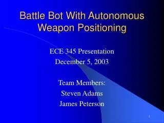
Battle Bot With Autonomous Weapon Positioning. ECE 345 Presentation December 5, 2003 Team Members: Steven Adams James Peterson. Introduction. A Battle Bot is a remote controlled vehicle that is intended to combat other battle bots and to avoid hazards. Objectives.

Battle Bot With Autonomous Weapon Positioning
E N D
Presentation Transcript
Battle Bot With Autonomous Weapon Positioning ECE 345 Presentation December 5, 2003 Team Members: Steven Adams James Peterson
Introduction • A Battle Bot is a remote controlled vehicle that is intended to combat other battle bots and to avoid hazards
Objectives • Design a bot that is controlled remotely • To design the ability to position and attack autonomously • Competition ready • Structurally sound body
Design Overview Interrupt Controller AI and Arm Controller Attacking Motor Radio Controller Receiver Speed Controller Driving Motor
Power • Need enough power to last the round(~10 min) • Battery type 1.2V, 2000mAH Ni-MH camera batteries 6A max output Rechargeable • Battery packs 4-12V battery packs 4-6V battery packs • Power supply calculations 60 Batteries * 1.2V * 6A = 432W max output power 60 Batteries * 1.2V * 2AH = 144 Wh
Power • Power consumption calculations • 2 Speed controllers and 1 interrupt controller .5A * 5V = 2.5W • Main circuit, attacking motor, and sensors .6A * 6V = 3.6W • Driving motors 2 Motors * 3.5 A * 30V = 210 W • Total power required = 216.1W 144 Wh / 216.1 W = 40 minutes of operation
Motor Controller Features • Multiple Data Inputs • Radio Control Receiver • Attack Sequence for a set time • Drives the motor either forward or reverse
Motor Controller Extra Features • Power Monitor • Makes sure there is power applied to the circuit for the PIC to output pulses to the motor • Neutral Set • Sets the neutral of the controller to the neutral in the PIC • Useful so the exact neutral is set • Gain Set • Sets the gain of the controller to be stored in the PIC • May be implemented in the future for pulse rejection
Motor Controller Extra Features Cont… • Forward and Reverse Transitions • If the last pulse was in the positive direction and the current pulse should be in the negative direction then the last pulse length is reduced steadily until neutral is found and then the new pulse outputs, and vice versa. • Reduces strain on the motor • Attack Sequence • Outputs a set pulse to drive the motor forward
Attack 0= 0 Attack 1= 0 Normal Operation of the Motor Controller Forward Driving Pins Forward Driving Pins Forward Driving Pins Forward Driving Pins Time Time Time Time 0 0 0 0 T/2 T/2 T/2 T/2 T T T T Attack 0= 1 Attack 1= 0 Attack 0= 0 Attack 1= 1 Attack 0= 1 Attack 1= 1 Attack Sequence
Motor Controller Flow Chart Start No Neutral switch pressed? voltage to the PIC? Start of pulse? Attack 0? Attack 1? Yes No No No Yes Yes Yes No Yes No Attack 1? No Times the pulse and subtracts this count from neutral Outputs to pins 10 and 12 a short pulse and an equal output of low for a time T Pulse input high? Time the pulse and sets it as neutral Yes voltage to the PIC? Yes Yes Outputs to pins 10 and 12 a long pulse for a time T Decreases the last pulse steadily until neutral Forward Direction? gain switch pressed? No No Last pulse forward? Yes Reverse Time the pulse and sets it as the gain No Yes Outputs to pins 10 and 12 the difference of neutral and the pulse times a constant factor Yes Outputs low to all pins for a time T Last pulse reverse? Pulse input high? Yes Yes Pulse input high? No No Outputs to pins 9 and 11 the difference of the pulse and neutral times a constant factor Decreases the last pulse steadily until neutral No
Interrupt Controller Features • Detects if Channel 1(Attack) is triggered on the remote controller and outputs on pin 9 • Detects if Channel 4(Interrupt) is triggered on the remote controller and outputs on pin 8
Interrupt Controller Flow Chart No Start Start of interrupt pulse? Start of attack pulse? No Yes Yes Times the pulse and subtracts this count from neutral Times the pulse and subtracts this count from neutral Sets pin 9 to low Sets pin 8 to low Greater than neutral margin? Greater than neutral margin? No No Sets pin 9 to high Sets pin 8 to high Yes Yes
Attacking Motor Controller • Reversible current • Receives signal from the processor
Sensor Circuit • Sensors and receivers are in collimators • Receives the on/off command • Turns on and off the IR LEDs Wavelength = 880nm • Transmits the data from the sensors back to the main circuit Peak sensitivity of the sensor is 880nm BIC pen Light Object BIC pen
Main Circuit Description • Cycles through the sensors • Gets analog data from the photo transistors • Converts data to a digital signal • Filters data • Processes the information • Controls the attacking arm • Interrupt capable
Processor Program Flow Chart Start Attack Initialize Retract arm Get sensor number Attack YES Left sensor triggered? Get sensor data –LED off Retract arm NO Get sensor data –LED on Sensor #4-7? NO NO NO Increment sensor number Right sensor triggered? Interrupt ? YES Hard left turn Sensor number = 16? NO YES YES YES Light left turn NO YES NO Sensor #8-11? YES Interrupt ? Attack? YES NO Hard right turn Attacking sensors triggered? YES Light right turn NO
Sensor Testing • Determine background radiation • Program filter Artificial lighting flickers Prevent underflow or else a false positive is triggered • Test different types of objects and vary the distance • Set thresholds
Sensor Test Data • Test unfiltered signal to determine how background radiation is a factor
Sensor Test Data • Simulate another bot and test filter
Sensor Test Data • Simulate battle arena walls and irregular metallic surfaces
Main Circuit Testing • Use a metal panel to test each sensor Make sure each sensor triggers the desired response • Correct attack timing Make sure the arm becomes fully extended and fully retracted
CH 2 CH 4 CH 3 CH 1 CH 1 Pulses for Remote Control
Challenges • Processor 2 different micro-controllers to program • Object detection Filtering signal, sensor timing • Mechanical Driving motor interface Variable speed control Attacking motor interface • Construction Making sure soldering joints will withstand combat Making sure body will withstand combat • Component failure • Controller interface PWM
Successes • Sensors triggered and proper response initiated • No false positive responses • Attacking motor functioning with circuit • Variable speed control • Interrupt/attack triggering
Recommendations • Increase the amount of emitters • Integrate the actual attacking arm • Optimal sensor placement • Further modifications to the bot body Guard rails for circuit protection Attacking arm and top Sensor/emitter holes on side of bot Increase weaponry Wire ties No breadboards Decrease clearance with a skirt • Increase durability of battery packs
Special Thanks • Professor Swenson for helping us with the optical aspects of our project • Mark Wiegert for guiding us throughout our building of our project • Microchip for donating several different PICs for free • Metal Shop for fabricating the battle bot and helping with the layout of the bot • Parts Shop for giving us several components