Download
1 / 31
1.19k likes | 3.49k Vues
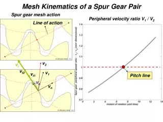
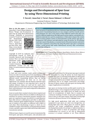
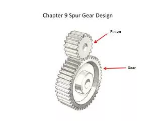
Chapter 9 Spur Gear Design. Pinion. Gear. Lecture Steps:. Quick review, gear geometry (Chapter 8) Transmitted loads (overhead) Review bending stress, bending stress number, St, allowable bending stress number, Sat and adjusted allowable bending stress number, S’at .

E N D
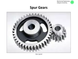
Chapter 9 Spur Gear Design Pinion Gear
Lecture Steps: • Quick review, gear geometry (Chapter 8) • Transmitted loads (overhead) • Review bending stress, bending stress number, St, allowable bending stress number, Sat and adjusted allowable bending stress number, S’at. • Review contact stress number, Sc, allowable contact stress number, Sac and adjusted allowable contact stress number S’ac. • Overview gear design steps. • Example(s) gear design!! handout
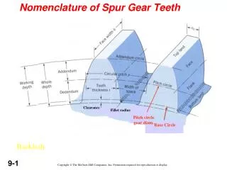
Quick review: Bending Stress No: Required Allowable Bending Stress No: Contact Stress No: Required Allowable Contact Stress No:
Steps for Gear Drive Design: • From design requirements, identify speed of pinion, nP, desired output speed of gear, nG, and power to be transmitted, P. • Choose type of material for the gears (steel, cast iron, bronze, etc.) • Determine overload factor, Ko, using table 9-5 • Calculated Pdes = KoP and calculate a trial value for the diametral pitch, Pd (for steel use Figure 9-27). Note diametral pitch must be a standard size (see Table 8-2). • Note, as Pd decreases, tooth size increases thus bringing down St and Sc. But….. As Pd increases, # teeth increases and gear train runs smoother and quiter and the drive gets smaller as well!
Steps for Gear Drive Design: • Specify Np and NG to meet VR requirement. Calculate center distance, D, OD to make sure there aren’t any interference issues. • Specify face width using recommended range: 8/Pd < F < 16/Pd. • Remember, increasing face width reduces St and Sc but consider alignment factor. Face width is normally less than 2X Dp. • Compute transmitted load, Wt, pitch line speed, vt, quality number, Qv, and other factors required for calculating bending stress and contact stress. • Calculate St and required Sat. Does material in 2 meet Sat #? No – then select new material or define new geometry (step 4). If yes, continue to 9. • Calculate Sc and required Sac. Does material in 2 meet Sac? No – then select new material to meet Sac and Sat or define new geometry (step 4). If yes, continue to 10. • Summarize design
Problem # 9.61 A gear pair is to be a part of the drive for a milling machine requiring 20 hp with the pinion speed at 550 rpm and the gear speed to be between 180 and 190 rpm. Given: Driven = Milling Machine Power = 20 hp Pinion Speed = 550 rpm Output Speed = 180 -190 rpm ≈ 185 rpm Continuous Use = 30,000 hours Find: Compact Gear Design
Solution: Design Power: Assume: Light Shock Driver and Moderate Shock Driven Ko = 1.75 (Table 9-5, page 389) PDesign = (Ko)(PInput) = (1.75)(20hp) = 35hp
Trial Size Pick Sizes Pd = 5 T/in Dp = 4.80 in DG = 14.2 in Np = 24 teeth NG = 71 teeth Check physical size!!
Center Distance Pitch Line Speed Tangential Load Note: Use Input Power Here as Ko is applied Later! Face Width
Assumptions: Design Decisions Quality Number, Qv = 6 (Table 9-2, Page 378) Steel Pinion Steel Gear More precision, higher quality number! Cp = 2300 (Table 9-9, Page 400) Softer material, more relative deformation, therefore contact area increases and stress decreases
Geometry Factors Pinion: JP = .36 Gear: JG = .415 Figure 9-17, Page 387
Geometry Factors Cont… Page 402 I = .108
Load Distribution Factor Equation 9-16, Page 390; Equation is solved on next slide Page
Load Distribution Factor Cont… Size Factor Page 389 ks = 1.0 since Pd ≥ 5
Rim Thickness Factor Page For this problem, specify a solid gear blank KB = 1.00 KB = 1.00 for mB = 1.2 or larger
Rim Thickness Factor Cont… We are assuming a solid gear blank for this problem, but if not then use: Min Rim Thickness = (1.2)(.45 in) = .54 in Min back-up ratio
Safety Factor SF = 1.25 (Mid-Range) Hardness Ratio CH =1.00 for early trials until materials have been specified. Then adjust CH if significant differences exist in the hardness of the pinion and the gear. Reliability Page 396 KR = 1.5 (for 1 in 10,000 failures)
Dynamic Factor Kv Page 393
Dynamic Factor Cont… Kv Qv comes from Figure 9-21 Kv can be calculated like in above equations or taken from Figure 9-21. Equations are more accurate.
Design Life Ncp = (60)(L)(n)(q) L = 30,000 hours from Table 9-7 n = 550 rpm q = 1 contacts Ncp = (60)(30,000 hours)(550 rpm)(1 contact) = 9.9x10⁸ cycles NcG = (60)(30,000 hours)( 185.92 rpm)(1 contact) = 3.34656x10⁸ cycles
Stress Cycle Factors Page 395
Stress Cycle Factors Cont… Page 403
Bending Stress Numbers Pinion: Gear:
Required Contact Stress Allowable: Pinion: Gear:
Hardness Numbers BENDING (Grade 1) Page 379 Pinion Bending Satp = 34,324.5 psi = HB 270 Gear Bending These stresses are OK SatG = 28,741.9 psi = HB 215 Go to appendix A3 or A4 and spec out material that meets this hardness requirement! Example AISI 1040, Temper at 900 F
Hardness Numbers CONTACT (Grade 1) Page 380 Pinion Contact Sacp = 261,178 psi Gear Contact These Stresses are WAY too HIGH! Values are off table! SacG = 245,609 psi
Summary of Problem Contact stresses are too High. Must iterate until stress are low enough until a usable material can be found. NOTE: Contact Stress generally controls. If material cannot be found for bending, contact stress is too high! Iterate! Decrease Pdand increase F Excel is a GREAT tool to use for these Iterations. This problem solved after third iteration using Excel
Guidelines for Adjustments in Successive Iterations. • Decreasing the numerical value of the diametral pitch results in larger teeth and generally lower stresses. Also, the lower value of the pitch usually means a larger face width, which decreases stress and increases surface durability. • Increase the diameter of the pinion decreases the transmitted load, generally lowers the stresses and improves surface durability. • Increase the face width lowers the stress and improves surface durability but less impact than either the pitch or pitch diameter. • Gears with more and smaller teeth tend to run more smoothly and quietly than gears with fewer and larger teeth. • Standard values of diametral pitch should be used for ease of manufacture and lower cost (See table 8-2). • Use high alloy steels with high surface hardness – results in the most compact system but the cost is higher. • Use gears with high quality number, Qv – adds cost but lowers load distribution factor, Km. • The number of teeth in the pinion should be as small as possible to make the system compact. But the possibility of interference is greater with fewer teeth. Check Table 8-6 to ensure no interference will occur.