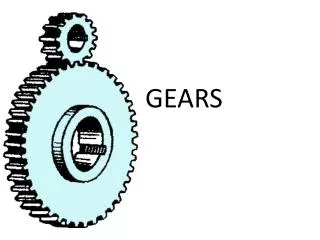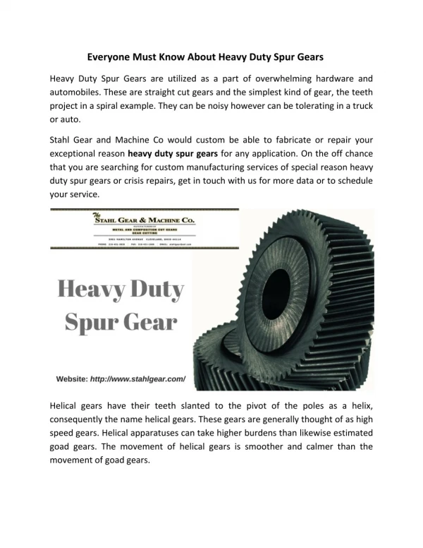
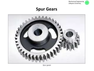

Spur Gears
E N D
Presentation Transcript
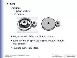
Introduction The slipping of a belt or rope is a common phenomenon, in the transmission of motion or power between two shafts. The effect of slipping is to reduce the velocity ratio of the system. In precision machines, in which a definite velocity ratio is of importance (as in watch mechanism), the only positive drive is by gears or toothed wheels. A gear drive is also provided, when the distance between the driver and the follower is very small. Friction Wheels The motion and power transmitted by gears is kinematically equivalent to that transmitted by frictional wheels or discs. In order to understand how the motion can be transmitted by two toothed wheels, consider two plain circular wheels A and B mounted on shafts. The wheels have sufficient rough surfaces and press against each other as shown in Fig. 1. The wheel B will be rotated by the wheel A so long as the tangential force exerted by the wheel A does not exceed the maximum frictional resistance between the two wheels. But when the tangential force (P) exceeds the *frictional resistance (F), slipping will take place between the two wheels.
In order to avoid the slipping, a number of projections (called teeth) as shown in Fig. 2 are provided on the periphery of the wheel A which will fit into the corresponding recesses on the periphery of the wheel B. A friction wheel with the teeth cut on it is known as gear or toothed wheel. The usual connection to show the toothed wheels is by their pitch circles. Fig. 1. Friction wheels. Fig. 2. Gear or toothed wheel.
Advantages and Disadvantages of Gear Drives The advantages and disadvantages of the gear drive as compared to other drives, i.e. belt, rope and chain drives : Advantages It transmits exact velocity ratio. It may be used to transmit large power. It may be used for small centre distances of shafts. It has high efficiency. It has reliable service. It has compact layout. Disadvantages Since the manufacture of gears require special tools and equipment, therefore it is costlier than other drives. The error in cutting teeth may cause vibrations and noise during operation. It requires suitable lubricant and reliable method of applying it, for the proper operation of gear drives.
4. Classification of Gears The gears or toothed wheels may be classified as follows : 1. According to the position of axes of the shafts : (a) Parallel, (b) Intersecting, and (c) Non-intersecting and non-parallel. spur gears : the two parallel and co-planar shafts connected by the gears and have teeth parallel to the axis of the wheel as shown in Fig. 2. Another name is helical gearing, in which the teeth are inclined to the axis. The single and double helical gears (herringbone gears) connecting parallel shafts are shown in Fig. 3 (a) and (b) respectively. The object of the double helical gear is to balance out the end thrusts that are induced in single helical gears when transmitting load. A pair of spur gears are kinematically equivalent to a pair of cylindrical discs, keyed to a parallel shaft having line contact. bevel gears : the two non-parallel or intersecting, but coplaner shafts connected by gears is shown in Fig. 3 (c). The bevel gears, like spur gears may also have their teeth inclined to the face of the bevel, in which case they are known as helical bevel gears.skew bevel gears or spiral gears : the two non-intersecting and non-parallel i.e. non-coplanar shafts connected by gears is shown in Fig. 28.3 (d). This type of gearing also have a line contact, the rotation of which about the axes generates the two pitch surfaces known as hyperboloids.
2. According to the peripheral velocity of the gears : Low velocity, less than 3 m/s (b) Medium velocity, 3 and 15 m/s (c) High velocity, more than 15 m/s 3. According to the type of gearing : (a) External gearing, (b) Internal gearing, and (c) Rack and pinion. external gearing : the gears of the two shafts mesh externally with each other as shown in Fig. 4 (a). The larger wheel is called spur wheel or gear and the smaller wheel is called pinion. internal gearing : the gears of the two shafts mesh internally with each other as shown in Fig. 4 (b). The larger wheel is called annular wheel and the smaller wheel is called pinion. rack and pinion : the gear of a shaft meshes externally and internally with the gears in a *straight line, as shown in Fig.5. The straight line gear is called rack and the circular wheel is called pinion. 4. According to the position of teeth on the gear surface. The teeth on the gear surface may be (a) Straight, (b) Inclined, and (c) Curved.
Fig. 4 Fig. 5. Rack and pinion.
5. Terms used in Gears The terms are illustrated in Fig. 6. Pitch circle. It is an imaginary circle which by pure rolling action, would give the same motion as the actual gear. Pitch circle diameter. It is the diameter of the pitch circle. The size of the gear is usually specified by the pitch circle diameter. It is also called as pitch diameter. Pitch point. It is a common point of contact between two pitch circles. Pitch surface. It is the surface of the rolling discs which the meshing gears have replaced at the pitch circle. Fig. 6. Terms used in gears.
Pressure angle or angle of obliquity : the angle between the common normal to two gear teeth at the point of contact and the common tangent at the pitch point. It is usually denoted by φ. The standard pressure angles are 1 14 /2° and 20°. Addendum : the radial distance of a tooth from the pitch circle to the top of the tooth. Dedendum : the radial distance of a tooth from the pitch circle to the bottom of the tooth. Addendum circle : the circle drawn through the top of the teeth and is concentric with the pitch circle. Dedendum circle (root circle): the circle drawn through the bottom of the teeth. Note : Root circle diameter = Pitch circle diameter × cos φ, where φ is the pressure angle. Circular pitch, pc : the distance measured on the circumference of the pitch circle from a point of one tooth to the corresponding point on the next tooth. Circular pitch, pc = π D/T where D = Diameter of the pitch circle, and T = Number of teeth on the wheel. A little consideration will show that the two gears will mesh together correctly, if the two wheels have the same circular pitch. Note : If D1 and D2 are the diameters of the two meshing gears having the teeth T1 and T2 respectively; then for them to mesh correctly,
Diametral pitch, pd : the ratio of number of teeth to the pitch circle diameter in millimetres. Module, m : the ratio of the pitch circle diameter in millimetres to the number of teeth. Module, m = D / T Note : The recommended series of modules in Indian Standard are 1, 1.25, 1.5, 2, 2.5, 3, 4, 5, 6, 8, 10, 12, 16, 20, 25, 32, 40 and 50. The modules 1.125, 1.375, 1.75, 2.25, 2.75, 3.5, 4.5,5.5, 7, 9, 11, 14, 18, 22, 28, 36 and 45 are of secondchoice. Clearance : the radial distance from the top of the tooth to the bottom of the tooth, in a meshing gear. A circle passing through the top of the meshing gear is known as clearance circle. Total depth : the radial distance between the addendum and the dedendum circle of a gear. It is equal to the sum of the addendum and dedendum. Working depth : radial distance from the addendum circle to the clearance circle. It is equal to the sum of the addendum of the two meshing gears. 16. Tooth thickness : the width of the tooth measured along the pitch circle.
Tooth space : the width of space between the two adjacent teeth measured along the pitch circle. Backlash : the difference between the tooth space and the tooth thickness, as measured on the pitch circle. Face of the tooth : surface of the tooth above the pitch surface. Top land : the surface of the top of the tooth. Flank of the tooth : the surface of the tooth below the pitch surface. Face width : the width of the gear tooth measured parallel to its axis. Profile : the curve formed by the face and flank of the tooth. Fillet radius : the radius that connects the root circle to the profile of the tooth. Path of contact : the path traced by the point of contact of two teeth from the beginning to the end of engagement. Length of the path of contact : the length of the common normal cut-off by the addendum circles of the wheel and pinion. Arc of contact : the path traced by a point on the pitch circle from the beginning to the end of engagement of a given pair of teeth, consists of two parts, i.e. (a) Arc of approach : the portion of the path of contact from the beginning of the engagement to the pitch point. (b) Arc of recess : the portion of the path of contact from the pitch point to the end of the engagement of a pair of teeth. Note : The ratio of the length of arc of contact to the circular pitch is known as contact ratio i.e. number of pairs of teeth in contact.
6. Condition for Constant Velocity Ratio of Gears–Law of Gearing The two teeth come in contact at point Q, and the wheels rotate in the directions as shown in the Fig. 7. Let T T be the common tangent and MN be the common normal to the curves at point of contact Q. From the centres O1 and O2, draw O1M and O2N perpendicular to MN. A little consideration will show that the point Q moves in the direction QC, when considered as a point on wheel 1, and in the direction QD when considered as a point on wheel 2. Let v1 and v2 be the velocities of the point Q on the wheels 1 and 2 respectively. If the teeth are to remain in contact, then the components of these velocities along the common normal MN must be equal.
Fig. 7. Law of gearing. If D1 and D2 are pitch circle diameters of wheel 1 and 2 having teeth T1 and T2 respectively, then velocity ratio,
7. Forms of Teeth in actual practice, following are the two types of teeth commonly used. Cycloidal teeth ; and 2. Involute teeth. 8. Cycloidal Teeth A cycloid is the curve traced by a point on the circumference of a circle which rolls without slipping on a fixed straight line. When a circle rolls without slipping on the outside of a fixed circle, the curve traced by a point on the circumference of a circle is known as epicycloid. On the other hand, if a circle rolls without slipping on the inside of a fixed circle, then the curve traced by a point on the circumference of a circle is called hypocycloid. Fig. 8. Construction of cycloidal teeth of a gear.
28.9 Involute Teeth An involute of a circle is a plane curve generated by a point on a tangent, which rolls on the circle without slipping or by a point on a taut string which is unwrapped from a reel as shown in Fig. 10 (a). In connection with toothed wheels, the circle is known as base circle. Fig. 10. Construction of involute teeth.
From similar triangles O2 NP and O1 MP, which determines the ratio of the radii of the two base circles. The radii of the base circles is given by O1M = O1 P cos φ, and O2N = O2 P cos φ where φ is the pressure angle or the angle of obliquity. Also the centre distance between the base circles
10. Comparison Between Involute and Cycloidal Gears In actual practice, the involute gears are more commonly used as compared to cycloidal gears, due to the following advantages : the advantages of involute gears : The most important advantage of the involute gears is that the centre distance for a pair of involute gears can be varied within limits without changing the velocity ratio. This is not true for cycloidal gears which requires exact centre distance to be maintained. In involute gears, the pressure angle, from the start of the engagement of teeth to the end of the engagement, remains constant. It is necessary for smooth running and less wear of gears. But in cycloidal gears, the pressure angle is maximum at the beginning of engagement, reduces to zero at pitch point, starts increasing and again becomes maximum at the end of engagement. This results in less smooth running of gears. The face and flank of involute teeth are generated by a single curve whereas in cycloidal gears, double curves (i.e. epicycloid and hypocycloid) are required for the face and flank respectively.
The advantages of cycloidal gears : Since the cycloidal teeth have wider flanks, therefore the cycloidal gears are stronger than the involute gears for the same pitch. Due to this reason, the cycloidal teeth are preferred specially for cast teeth. In cycloidal gears, the contact takes place between a convex flank and concave surface, whereas in involute gears, the convex surfaces are in contact. This condition results in less wear in cycloidal gears as compared to involute gears. However the difference in wear is negligible. In cycloidal gears, the interference does not occur at all. Though there are advantages of cycloidal gears but they are outweighed by the greater simplicity and flexibility of the involute gears.
11. Systems of Gear Teeth The following four systems of gear teeth are commonly used in practice. 14 1/2° Composite system, 14 1/2° Full depth involute system, 20° Full depth involute system, 20° Stub involute system. The 14 1/2° composite system is used for general purpose gears. It is stronger but has no interchangeability. The tooth profile of this system has cycloidal curves at the top and bottom and involute curve at the middle portion. The teeth are produced by formed milling cutters or hobs. The tooth profile of the 14 1/2° full depth involute system was developed for use with gear hobs for spur and helical gears. The tooth profile of the 20° full depth involute system may be cut by hobs. The increase of the pressure angle from 14 1/2° to 20° results in a stronger tooth, because the tooth acting as a beam is wider at the base. The 20° stub involute system has a strong tooth to take heavy loads.
12 Standard Proportions of Gear Systems The following table shows the standard proportions in module (m) for the four gear systems as discussed in the previous article. Table 1. Standard proportions of gear systems.
13. Interference in Involute Gears the phenomenon when the tip of a tooth undercuts the root on its mating gear is known asinterference. The points M and N are called interference points. Fig. 11. Interference in involute gears.
Note : In order to avoid interference, the limiting value of the radius of the addendum circle of the pinion (O1 N) and of the wheel (O2 M), may be obtained as follows : From Fig. 11, we see that
14. Minimum Number of Teeth on the Pinion in Order to AvoidInterference Table 2. Minimum number of teeth on the pinion in order to avoid interference. The number of teeth on the pinion (TP) in order to avoid interference may be obtained from the following relation :
15. Gear Materials The material used for the manufacture of gears depends upon the strength and service conditions like wear, noise etc. The gears may be manufactured from metallic or non-metallic materials. The metallic gears with cut teeth are commercially obtainable in cast iron, steel and bronze. The nonmetallic materials like wood, rawhide, compressed paper and synthetic resins like nylon are used for gears, especially for reducing noise. Table 3. Properties of commonly used gear materials.
16. Design Considerations for a Gear Drive In the design of a gear drive, the following data is usually given : 1. The power to be transmitted. 2. The speed of the driving gear, 3. The speed of the driven gear or the velocity ratio, and 4. The centre distance. The following requirements must be met in the design of a gear drive : (a) The gear teeth should have sufficient strength so that they will not fail under static loading or dynamic loading during normal running conditions. (b) The gear teeth should have wear characteristics so that their life is satisfactory. (c) The use of space and material should be economical. (d) The alignment of the gears and deflections of the shafts must be considered because they effect on the performance of the gears. (e) The lubrication of the gears must be satisfactory.
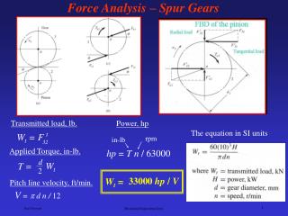
17. Beam Strength of Gear Teeth – Lewis Equation Consider each tooth as a cantilever beam loaded by a normal load (WN) as shown in Fig. 12. It is resolved into two components i.e. tangential component (WT) and radial component (WR) acting perpendicular and parallel to the centre line of the tooth respectively. The tangential component (WT) induces a bending stress which tends to break the tooth. The radial component (WR) induces a compressive stress of relatively small magnitude, therefore its effect on the tooth may be neglected. Fig. 12. Tooth of a gear.
The maximum value of the bending stress (or the permissible working stress), at the section BC is given by σw = M.y / I ...(i) where M = Maximum bending moment at the critical section BC = WT × h, WT = Tangential load acting at the tooth, h = Length of the tooth, y = Half the thickness of the tooth (t) at critical section BC = t/2, I = Moment of inertia about the centre line of the tooth = b.t3/12, b = Width of gear face. Substituting the values for M, y and I in equation (i), we get In this expression, t and h are variables depending upon the size of the tooth (i.e. the circular pitch) and its profile.
The quantity y is known as Lewisform factor or tooth form factor and WT (which is the tangential load acting at the tooth) is called the beam strength of the tooth. therefore in order to find the value of y, the quantities t, h and pc may be determined analytically or measured from the drawing similar to Fig. 12. The value of y in terms of the number of teeth may be expressed as follows :
18. Permissible Working Stress for Gear Teeth in the Lewis Equation The permissible working stress (σw) in the Lewis equation depends upon the material for which an allowable static stress (σo) may be determined. The allowable static stress is the stress at the elastic limit of the material. It is also called the basic stress. According to the Barth formula, the permissible working stress, σw = σo × Cv, where σo = Allowable static stress, and Cv = Velocity factor. The values of the velocity factor (Cv) are given as follows : v is the pitch line velocity in metres per second.
19. Dynamic Tooth Load In the previous article, the velocity factor was used to make approximate allowance for the effect of dynamic loading. The dynamic loads are due to the following reasons : 1. Inaccuracies of tooth spacing, 2. Irregularities in tooth profiles, and 3. Deflections of teeth under load. A closer approximation to the actual conditions may be made by the use of equations based on extensive series of tests, as follows : WD = WT + WI where WD = Total dynamic load, WT = Steady load due to transmitted torque, and WI = Increment load due to dynamic action. The increment load (WI) depends upon the pitch line velocity, the face width, material of the gears, the accuracy of cut and the tangential load.
For average conditions, the dynamic load is determined by using the following Buckingham equation, i.e. where WD = Total dynamic load in newtons, WT = Steady transmitted load in newtons, v = Pitch line velocity in m/s, b = Face width of gears in mm, and C = A deformation or dynamic factor in N/mm. A deformation factor (C) depends upon the error in action between teeth, the class of cut of the gears, the tooth form and the material of the gears.
Table 5. Values of deformation factor (C ). The value of C in N/mm may be determined by using the following relation :
where K = A factor depending upon the form of the teeth. = 0.107, for 14 1/2 ° full depth involute system. = 0.111, for 20° full depth involute system. = 0.115 for 20° stub system. EP = Young's modulus for the material of the pinion in N/mm2. EG = Young's modulus for the material of gear in N/mm2. e = Tooth error action in mm. The maximum allowable tooth error in action (e) depends upon the pitch line velocity (v) and the class of cut of the gears. Table 6. Values of maximum allowable tooth error in action (e) verses pitch line velocity, for well cut commercial gears.
20. Static Tooth Load The static tooth load (also called beam strength or endurance strength of the tooth) is obtained by Lewis formula by substituting flexural endurance limit or elastic limit stress (σe) in place of permissible working stress (σw). ∴ Static tooth load or beam strength of the tooth, Table 8. Values of flexural endurance limit.
For safety, against tooth breakage, the static tooth load (WS) should be greater than the dynamic load (WD). Buckingham suggests the following relationship between WS and WD. For steady loads, WS ≥ 1.25 WD For pulsating loads, WS ≥ 1.35 WD For shock loads, WS ≥ 1.5 WD Note : For steel, the flexural endurance limit (σe) may be obtained by using the following relation : σe = 1.75 × B.H.N. (in MPa)
21. Wear Tooth Load The maximum load that gear teeth can carry, without premature wear, depends upon the radii of curvature of the tooth profiles and on the elasticity and surface fatigue limits of the materials. The maximum or the limiting load for satisfactory wear of gear teeth, is obtained by using the following Buckingham equation, i.e.
According to Buckingham, the load stress factor is given by the following relation : Table 9. Values of surface endurance limit. Notes : 1. The surface endurance limit for steel may be obtained from the following equation : σes = (2.8 × B.H.N. – 70) N/mm2 2. The maximum limiting wear load (Ww) must be greater than the dynamic load (WD).
22. Causes of Gear Tooth Failure The different modes of failure of gear teeth and their possible remedies to avoid the failure, are as follows : Bending failure. Every gear tooth acts as a cantilever. If the total repetitive dynamic load acting on the gear tooth is greater than the beam strength of the gear tooth, then the gear tooth will fail in bending, i.e. the gear tooth will break. In order to avoid such failure, the module and face width of the gear is adjusted so that the beam strength is greater than the dynamic load. Pitting. It is the surface fatigue failure which occurs due to many repetition of Hertz contact stresses. The failure occurs when the surface contact stresses are higher than the endurance limit of the material. The failure starts with the formation of pits which continue to grow resulting in the rupture of the tooth surface. In order to avoid the pitting, the dynamic load between the gear tooth should be less than the wear strength of the gear tooth. Scoring. The excessive heat is generated when there is an excessive surface pressure, high speed or supply of lubricant fails. It is a stick-slip phenomenon in which alternate shearing and welding takes place rapidly at high spots. This type of failure can be avoided by properly designing the parameters such as speed, pressure and proper flow of the lubricant, so that the temperature at the rubbing faces is within the permissible limits.
Abrasive wear. The foreign particles in the lubricants such as dirt, dust or burr enter between the tooth and damage the form of tooth. This type of failure can be avoided by providing filters for the lubricating oil or by using high viscosity lubricant oil which enables the formation of thicker oil film and hence permits easy passage of such particles without damaging the gear surface. Corrosive wear. The corrosion of the tooth surfaces is mainly caused due to the presence of corrosive elements such as additives present in the lubricating oils. In order to avoid this type of wear, proper anti-corrosive additives should be used.
23. Design Procedure for Spur Gears The following procedure may be followed : First of all, the design tangential tooth load is obtained from the power transmitted and the pitch line velocity by using the following relation : * We know that circular pitch, Thus, the pitch line velocity may also be obtained by using the following relation, i.e.
Table 10. Values of service factor. 2. Apply the Lewis equation as follows : Notes : (i) The Lewis equation is applied only to the weaker of the two wheels (i.e. pinion or gear). (ii) When both the pinion and the gear are made of the same material, then pinion is the weaker. (iii) When the pinion and the gear are made of different materials, then the product of (σw × y) or (σo × y) is the *deciding factor. The Lewis equation is used to that wheel for which (σw × y) or (σo × y) is less. (iv) The product (σw × y) is called strength factor of the gear. (v) The face width (b) may be taken as 3 pc to 4 pc (or 9.5 m to 12.5 m) for cut teeth and 2 pc to 3 pc (or 6.5 m to 9.5 m) for cast teeth.
3. Calculate the dynamic load (WD) on the tooth by using Buckingham equation, i.e. In calculating the dynamic load (WD), the value of tangential load (WT) may be calculated by neglecting the service factor (CS) i.e. WT = P / v, where P is in watts and v in m / s. 4. Find the static tooth load (i.e. beam strength or the endurance strength of the tooth) by using the relation, WS = σe.b.pc.y = σe.b.π m.y For safety against breakage, WS should be greater than WD. 5. Finally, find the wear tooth load by using the relation, Ww = DP.b.Q.K The wear load (Ww) should not be less than the dynamic load (WD).
Example 1. The following particulars of a single reduction spur gear are given : Gear ratio = 10 : 1; Distance between centres = 660 mm approximately; Pinion transmits 500 kW at 1800 r.p.m.; Involute teeth of standard proportions (addendum = m) with pressure angle of 22.5°; Permissible normal pressure between teeth = 175 N per mm of width. Find : 1. The nearest standard module if no interference is to occur; 2. The number of teeth on each wheel; 3. The necessary width of the pinion; and 4. The load on the bearings of the wheels due to power transmitted. Solution : Given : G = TG / TP = DG / DP = 10 ; L = 660 mm ; P = 500 kW = 500 × 103 W ; NP = 1800 r.p.m. ; φ = 22.5° ; WN = 175 N/mm width
1. Nearest standard module if no interference is to occur Let m = Required module, TP = Number of teeth on the pinion, TG = Number of teeth on the gear, DP = Pitch circle diameter of the pinion, and DG = Pitch circle diameter of the gear. We know that minimum number of teeth on the pinion in order to avoid interference,