Gears
Gears. Drawing Gear Teeth Spur Gears. Drawing Gear Teeth. The involute System The curved surface of the gear tooth profile must be of a definite geometric form if the gears are to operate smoothly with a minimum of noise and vibration. The most common form in use today is the involute

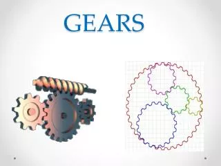
Gears
E N D
Presentation Transcript
Gears Drawing Gear Teeth Spur Gears
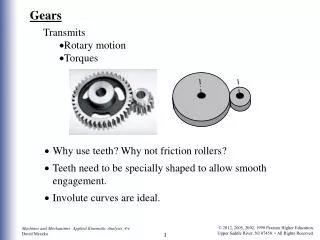
Drawing Gear Teeth The involute System The curved surface of the gear tooth profile must be of a definite geometric form if the gears are to operate smoothly with a minimum of noise and vibration. The most common form in use today is the involute profile. In the involute system, the shape of the tooth depends basically upon the pressure angle. The pressure angle is either 14 1/2 degrees or 20 degrees. The pressure angle determines the size of the base circle. The involute curve is generated from the base circle.
Drawing Gear Teeth Construction of the Base Circle Draw the pitch circle, the addendum circle, and the root circle. Add the vertical and horizontal center lines. Mark point (P) at the intersection of the vertical center line and the pitch circle. Construct a line perpendicular to the pressure angle (14 1/2 degrees) from the center of the pitch circle to at least the addendum circle. Construct a line perpendicular to the pressure angle line just constructed and passing through point (P). Mark this intersection as point (J). The base circle is constructed with the center being the center of the pitch circle and the radius equal to the distance from the center to point (J).
Drawing Gear Teeth Construction of the tooth profile Set off the tooth spacing along the pitch circle. You can use two methods to space the teeth; chordal thickness, or equal angles. chordal thickness: tc = D x (sin(90 degrees/N)) equal angles: angle = 360 degrees/ (2 x N) Draw the gear tooth face from point (P) to point (A) with a radius (R) derived from the Wellman's Involute Odontograph chart. The center of the radius is on the base circle. Do not use the radius values given directly from the chart. Each value must be divided then the Diametral Pitch (P) for the given gear. Drawing Radius (r) = Given radius from chart (r)/P Drawing Radius (R) = Given radius from chart (R)/P Draw the flank portion from (P) to (O) with a radius of (r) derived from the Wellman's Involute Odontograph chart as described above. The center of the radius is on the base circle. The portion of the tooth below the base circle is a straight line drawn to the gear center.
Drawing Gear Teeth Fillet the corners of the straight portion of the gear tooth and the root circle. The fillet radius can be derived from the following formulas: Fillet Radius = 1 1/2 x Clearance Fillet Radius = 1.5 (.157/P) Clearance = .157/P Clearance = B – A The remaining tooth profiles can be constructed using the same process, constructing a tooth profile through every other mark on the pitch circle. The opposite tooth profile can be drawn through the remaining marks located on the pitch circle be mirroring the above construction process.
Drawing Gear Teeth Wellman's Involute Odontograph Chart Number of 14 1/2 degrees 20 degrees Teeth R r R r 12 2.87 .079 3.21 1.31 13 3.02 .088 3.40 1.45 14 3.17 .097 3.58 1.60 15 3.31 1.06 3.76 1.75 16 3.46 1.16 3.94 1.90 17 3.60 1.26 4.12 2.05 18 3.74 1.36 4.30 2.20 19 3.88 1.46 4.48 2.35 20 4.02 1.56 4.66 2.51 21 4.16 1.66 4.84 2.66 22 4.29 1.77 5.02 2.82 23 4.43 1.87 5.20 2.89 24 4.57 1.98 5.37 3.14 25 4.70 2.08 5.55 3.29 26 4.84 2.19 5.73 3.45 27 4.97 2.30 5.90 3.61 28 5.11 2.41 6.08 3.77 29 5.24 2.52 6.25 3.93 30 5.37 2.63 6.43 4.10 31 5.51 2.74 6.60 4.26 32 5.64 2.85 6.78 4.42 33 5.77 2.96 6.95 4.58 34 5.90 3.07 7.13 4.74 35 6.03 3.18 7.30 4.91 36 6.17 3.29 7.47 5.07