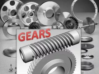
GEARS
GEARS. Gears. Rugged Durable Can transmit power with up to 98% efficiency Long service life. Motors. Motors convert electrical energy to mechanical energy. Mechanical energy moves our robot Motors drive the gears. http://www2.towerhobbies.com/cgi-bin/wti0001p?&I=LR9520&P=DS. Gears.


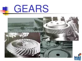
GEARS
E N D
Presentation Transcript
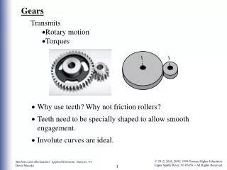
Gears • Rugged • Durable • Can transmit power with up to 98% efficiency • Long service life
Motors • Motors convert electrical energy to mechanical energy. • Mechanical energy moves our robot • Motors drive the gears http://www2.towerhobbies.com/cgi-bin/wti0001p?&I=LR9520&P=DS
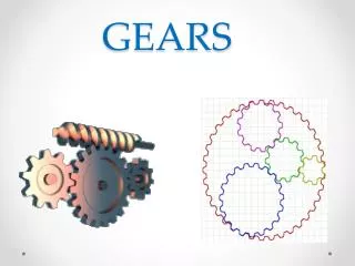
Gears • Spur • Flat • Pinion • Bevel • Crown • Worm • Rack and Pinion • Differential www.mathworks.com
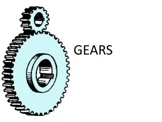
Gears • Toothed wheels fixed to an axle. • Drive gear – connected to the input axle. • Driven gear – connected to the output axle. • Gear train – when an number of gears are connected together. Number of driven teeth (output) Gear Ratio = Number of driver teeth (input)
Gear and Bearing Assemblies • Use as few views as possible • A full sectional view may be the only view necessary • Dimensions are normally omitted • Typically include balloons correlated with a parts list • May include torque data and lubricant information
Applications of Gears • Toys and Small Mechanisms– small, low load, low cost kinematic analysis • Appliance gears– long life, low noise & cost, low to moderate load kinematic & some stress analysis • Power transmission– long life, high load and speed kinematic & stress analysis • Aerospace gears– light weight, moderate to high load kinematic & stress analysis • Control gears– long life, low noise, precision gears kinematic & stress analysis
Spur Gears • Straight teeth mounted on parallel shafts • Many used at once to create very large gear reductions • Flat • Pinion http://en.wikipedia.org/wiki/Gear#Worm_gear
Internal gears – teeth are inclined to the axis of rotation, the angle provides more gradual engagement of the teeth during meshing, transmits motion between parallel shafts. Helical gears Types of Gears Gear (large gear) Spur gears – tooth profile is parallel to the axis of rotation, transmits motion between parallel shafts. Pinion (small gear) Mechanical Engineering Dept.
Spur Gear Terminology • Teeth are straight and parallel to the gear shaft axis • Establish gear tooth profile using an involute curve • Basic rule: • No fewer than 13 teeth on the running gear and 26 teeth on the mating gear
Spur Gear Terminology • Pressure angle • 14.5°and 20°are standard • Diametral pitch • Gear accuracy • Maximum tooth-to-tooth tolerances allowed, as specified by the American Gear Manufacturers Association (AGMA) • Several additional formulas and specifications
Bevel Gears • Gears that mesh at an angle, usually 90° • Changes the direction of rotation http://science.howstuffworks.com/gear4.htm
Bevel Gears • Shafts of the gear and pinion can intersect at 90°or any desired angle • Provide for a speed change between the gear and pinion, unless designed as miter gears
Straight bevel gear Spiral bevel gear Types of Gears Bevel gears – teeth are formed on a conical surface, used to transfer motion between non-parallel and intersecting shafts. Mechanical Engineering Dept.
Crown Gears • Special form of bevel gear • Has right angles to the plane of the wheel http://www.plastic-gear-manufacturer.com/industrial-gear.htm
Worm Gears • Changes the direction of turning motion by 90° • Decreases the speed of turning from screw to gear and increases the force http://blogs.toolbarn.com/brianm/labels/Tool%20Inner%20Workings.html
Worm Gears • Use a worm and worm gear • Large speed reduction in a small space • Worm locks in place when not in operation
Rack and Pinion • Converts rotary motion to back and forth motion http://en.wikipedia.org/wiki/Gear#Worm_gear
Rack and Pinion • Spur pinion operating on a flat straight bar rack • Converts rotary motion into straight-line motion
Differential Gears • Splits torque two ways, allowing each output to spin at a different speed http://nxtasy.org/wp-content/uploads/2006/08/Differential2-00.html
Spur Gears • Transmit motion and power between parallel shafts • Two basic types: • External spur gears • Internal spur gears • Cluster gears
Spur Gears • Advantages: • Economical • Simple design • Ease of maintenance • Disadvantages: • Less load capacity • Higher noise levels
Helical Gears • Teeth cut at an angle • Allows more than one tooth to be in contact
Crossed Helical Gears • Also known as: • Right angle helical gears • Spiral gears • Low load-carrying capabilities
Helical Gears • Carry more load than equivalent-sized spur gears • Operate more quietly and smoothly • Develop end thrust • Can be eliminated using double helical gears, such as a herringbone gear
Gear Assemblies • LEGO™ Technic 1031 Gear Assembly Activity • Gearing up and Gearing down http://reprap.blogspot.com/2005_12_01_archive.html
Cool Site • http://nxtasy.org/ • Includes plans! • NXT Aerial Ropeway • NXT Gymnast • NXTWay-G: Balancing with a Gyro Sensor Created by Dr. T.E. Varnado
GEARS-Wheel and Axel • Each gear in a series reverses the direction of rotation of the previous gear. The smaller gear will always turn faster than the larger gear.
Common Gear Materials • Cast iron • Steel • Brass • Bronze alloys • Plastic
Gear Selection and Design • Often done through vendors’ catalogs or the use of standard formulas • American Gear Manufacturers Association (AGMA) • AGMA 2000-A88, Gear Classification and Inspection Handbook - Tolerances and Measuring Methods for Unassembled Spur and Helical Gears, including Metric Equivalents • American Society of Mechanical Engineers (ASME) • ASME Y14.7.1 Gear Drawing Standards - Part 1: For Spur, Helical, Double Helical and Rack • ASME Y14.7.2 Gear and Spline Drawing Standards - Part 2: Bevel and Hypoid Gears
Gear Train • Increase or reduce speed • Change the direction of motion from one shaft to another
Splines • Often used when it is necessary for the gear or pulley to easily slide on the shaft • Can also be nonsliding • Stronger than keyways and keys
Intersecting Shafting Gears • Bevel gears • Face gears
Face Gears • Combination of bevel gear and spur pinion, or bevel gear and helical pinion • Requires less mounting accuracy • Caries less load
Nonintersecting Shafting Gears • Crossed helical gears • Hypoid gears • Worm gears
Hypoid Gears • Offset, nonintersecting gear shaft axes • Very smooth, strong, and quiet
Gear Trains • Transmit motion between shafts • Decrease or increase the speed between shafts • Change the direction of motion