GEARS
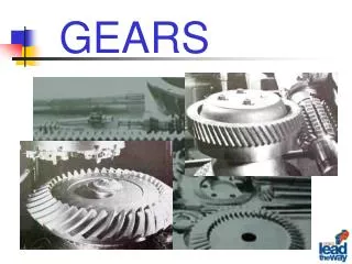
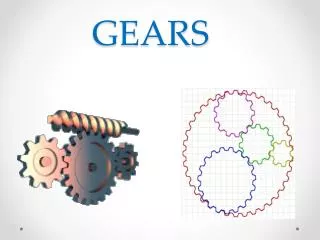
GEARS. DEFINITION OF GEARS Gears are toothed members which transmit power / motion between two shafts by meshing without any slip.

GEARS
E N D
Presentation Transcript
DEFINITION OF GEARS Gears are toothed members which transmit power / motion between two shafts by meshing without any slip. Hence, gear drives are also called positive drives. In any pair of gears, the smaller one is called pinion and the larger one is called gear immaterial of which is driving the other. When pinion is the driver, it results in step down drive in which the output speed decreases and the torque increases. On the other hand, when the gear is the driver, it results in step up drive in which the output speed increases and the torque decreases
CLASSIFICATION OF GEARS Gears are classified according to the shape of the tooth pair and disposition into spur, helical, double helical, straight bevel, spiral bevel and hypoid bevel, worm and spiral gears and this is shown in Fig
SPUR GEARS 1. Spur gears have their teeth parallel to the axis and are used for transmitting power between two parallel shafts. 2. They are simple in construction, easy to manufacture and cost less. 3.They have highest efficiency and excellent precision rating. 4. They are used in high speed and high load application in all types of trains and a wide range of velocity ratios. 5. Hence, they find wide applications right from clocks, household gadgets, motor cycles, automobiles, and railways to aircrafts. One such application is shown in Fig
Spur Gear Gearbox of a motor cycle using spur gears
HELICAL GEARS 1. Helical gears are used for parallel shaft drives. 2. They have teeth inclined to the axis .Hence for the same width, their teeth are longer than spur gears and have higher load carrying capacity. Their contact ratio is higher than spur gears and they operate smoother and quieter than spur gears. 3. Their precision rating is good. They are recommended for very high speeds and loads. 4. These gears find wide applications in automotive gearboxes as illustrated in Fig .Their efficiency is slightly lower than spur gears. The helix angle also introduces axial thrust on the shaft.
Helical Gear Automatic transmission of an automobile
DOUBLE HELICAL GEAR OR HERRINGBONE GEAR 1.Double helical or Herringbone gears used for transmitting power between two parallel shafts. 2.They have opposing helical teeth with or without a gap depending on the manufacturing method adopted. 3. Two axial thrusts oppose each other and nullify. Hence the shaft is free from any axial force. 4. Though their load capacity is very high, manufacturing difficulty makes them costlier than single helical gear. Their applications are limited to high capacity reduction drives like that of cement mills and crushers, one such application is exhibited in Fig.
Double Helical Gear Reduction gearbox of cement mill
INTERNAL GEAR 1. Internal gears are used for transmitting power between two parallel shafts. 2. In these gears, annular wheels are having teeth on the inner periphery. This makes the drive very compact. 3.Their precision rating is fair. They are useful for high load and high speed application with high reduction ratio. 4.Applications of these gears can be seen in planetary gear drives of automobile automatic transmissions ,reduction gearboxes of cement mills etc. 5. They are not recommended for precision meshes because of design, fabrication, and inspection limitations. They should only be used when internal feature is necessary. However, today precision machining capability has led to their usage even in position devices like antenna drives.
Internal Gear Internal Gear Pumps
Rack and Pinion Rack is a segment of a gear of infinite diameter. The tooth can be spur as or helical. 2. This type of gearing is used for converting rotary motion into translatory motion or visa versa. Typical example of rack and pinion applications are shown
Lathe carriage drive mechanism showing rack and pinion arrangement Radial drilling machine spindle movement with rack and pinion arrangement
STRAIGHT BEVEL GEAR Straight bevel gears are used for transmitting power between intersecting shafts. They can operate under high speeds and high loads. Their precision rating is fair to good. They are suitable for 1:1 and higher velocity ratios and for right-angle meshes to any other angles. Their good choice is for right angle drive of particularly low ratios. Application of the straight bevel drives is in automotive differentials, right angle drives of blenders and conveyors. A typical application of straight bevel used in differential application is shown in Fig.
Straight Bevel Gear Differential of an automobile
SPIRAL BEVEL GEAR Spiral bevel gears are also used for transmitting power between intersecting shafts. Because of the spiral tooth, the contact length is more and contact ratio is more. They operate smoother than straight bevel gears and have higher load capacity. But, their efficiency is slightly lower than straight bevel gear. Usage of spiral bevel gears in an automobile differential is shown Fig.
WORM GEAR Worm and worm gear pair consists of a worm, which is very similar to a screw and a worm gear, which is a helical gear. They are used in right-angle skew shafts. In these gears, the engagement occurs without any shock. The sliding action prevalent in the system while resulting in quieter operation produces considerable frictional heat. High reduction ratios 8 to 400 are possible. 4. Efficiency of these gears is low anywhere from 90% to 40 %. Their precision rating is fair to good. 5. They need good lubrication for heat dissipation and for improving efficiency. The drives are very compact.
Worm Gear Worm gearbox of a crane drive Worm gearing finds wide application in material handling and transportation machinery, machine tools, automobiles etc.
Spiral Gear Spiral gears are also known as crossed helical gears. They have high helix angle and transmit power between two non-intersecting non-parallel shafts. They have initially point contact under the conditions of considerable sliding velocities finally gears will have line contact. Hence, they are used for light load and low speed application such as instruments, sewing machine etc. Their precision rating is poor. Spiral gears are used in textile machineries.
Gear Terminology The function of a gear is to work smoothly while transmitting motion or torque. For this the angular velocity ratio at all times should remain constant.
Pitch surface: The surface of the imaginary rolling cylinder (cone, etc.) that replaces the toothed gear. Pitch circle: A normal section of the pitch surface. Addendum circle: A circle bounding the ends of the teeth, in a normal section of the gear. Dedendum circle or Root circle: The circle bounding the spaces between the teeth, in a normal section of the gear. Addendum: The radial distance between the pitch circle and the addendum circle. Dedendum: The radial distance between the pitch circle and the root circle. Clearance: The difference between the Dedendum of one gear and the addendum of the mating gear. Face of a tooth: That part of the tooth surface lying outside the pitch surface.
Flank of a tooth: The part of the tooth surface lying inside the pitch surface. Top land: The top surface of a gear tooth. Bottom land: The bottom surface of the tooth space. Circular thickness (tooth thickness): The thickness of the tooth measured on the pitch circle. It is the length of an arc and not the length of a straight line. Tooth space: The space between successive teeth. Width of space: The distance between adjacent teeth measured on the pitch circle. Backlash: The difference between the tooth thickness of one gear and the tooth space of the mating gear.
Circular pitch: It is the distance measured on the circumference of the pitch circle from a point of one tooth to the corresponding point on the next tooth. It is usually denoted by pc. Mathematically, Circular pitch, pc = π D/T where D = Diameter of the pitch circle, and T = Number of teeth on the wheel. The two gears will mesh together correctly, if the two wheels have the same circular pitch.
Diametral pitch: It is the ratio of number of teeth to the pitch circle diameter in millimetres. It denoted by pd. Mathematically, Diametral pitch, The product of the diametral pitch and the circular pitch equals π. Module : It is the ratio of the pitch circle diameter in millimetres to the number of teeth. It is usually denoted by m. Mathematically, Module, m = D / T The recommended series of modules in Indian Standard are 1, 1.25, 1.5, 2, 2.5, 3, 4, 5, 6, 8, 10, 12, 16, 20, 25, 32, 40 and 50
Fillet Radius: The small radius that connects the profile of a tooth to the root circle. Crowning: Grinding of tooth edges to prevent edge loading is known as crowning Base circle: An imaginary circle used in involute gearing to generate the involutes that form the tooth profiles. Pinion: The smallest of any pair of mating gears. Gear: The largest of the pair is called simply the gear.
Pitch point: The point of tangency of the pitch circles of a pair of mating gears. Common tangent: The line tangent to the pitch circle at the pitch point. Line of action: A line normal to a pair of mating tooth profiles at their point of contact. Pressure angle φ: The angle between the common normal at the point of tooth contact and the common tangent to the pitch circles. Pressure angle is also the angle between the line of action and the common tangent
Path of contact: It is the path traced by the point of contact of two teeth from the beginning to the end of engagement. Length of the path of contact. It is the length of the common normal cut-off by the addendum circles of the wheel and pinion. Arc of contact. It is the path traced by a point on the pitch circle from the beginning to the end of engagement of a given pair of teeth. The arc of contact consists of two parts, i.e. (a) Arc of approach. It is the portion of the path of contact from the beginning of the engagement to the pitch point. (b) Arc of recess. It is the portion of the path of contact from the pitch point to the end of the engagement of a pair of teeth.
LAW OF GEARING Let v1 and v2 be the velocities of the point Q on the wheels 1 and 2 respectively. If the teeth are to remain in contact, then the components of these velocities along the common normal MN must be equal.
“In order to maintain constant angular velocity ratio between two meshing gears, the common normal of the tooth profiles, at all contact points with in mesh, must always pass through a fixed point on the line of centers, called pitch point. “ “The fundamental law of gearing states that the angular velocity ratio between the gears of a gear set must remain constant throughout the mesh. This amounts to the following relationship: where the terminology for the above is as follows : D1 and D2 are pitch circle diameters of wheel 1 and 2 having teeth T1 and T2 respectively.
PROFILES SATISFYING LAW OF GEARS Profiles which can satisfy the law of gearing are : (a) involute (b) cycloidal and (c) circular arc or Novikov Among these, cycloidal was the first to be evolved. This is followed by the invention of involute profile which replaced many of the other profiles due to several technological advantages. Circular arc or Novikov profile has some advantages over the other profiles. But due to manufacturing difficulties, it did not become popular. However with powder metallurgy process it is slowly getting into industry now for specific application .
Involute Gear Tooth Profile Involute is the path generated by the end of a thread as it unwinds from a reel. Process :Imagine a reel with thread wound in the clockwise direction as in Fig. Tie a knot at the end of the thread. In the initial position, the thread is at B0 with knot on the reel at C0. Keeping the reel stationary, pull the thread and unwind it to position B1. The knot now moves from C0 to C1. If the thread is unwound to position B2 the knot moves to C2 position. In repeated unwinding, the taut thread occupies position B3, B4 while the knot moves to C3, C4 positions. Connect these points C0 to C4 by a smooth curve, the profile obtained is nothing but an involute, the illustration of which is given below. This forms the right side part of the tooth profile. If similar process is repeated with thread wound on the reel in anticlockwise direction in the same position, it forms the left side part of the same tooth. The completely formed involute tooth is shown in Fig.
Involute profiles have special properties. Imagine two involute teeth in contact as shown in Fig If a normal is drawn at the contact point to the involute profile, it will be tangent to the generating circles. The profile will be involute above the base circle only. Below the base circle the profile will not be involute
Advantages of Involute Gears Variation in centre distance does not affect the velocity ratio. Pressure angle remains constant throughout the engagements which results in smooth running. 3. Straight teeth of basic rack for involute admit simple tools. Hence, manufacturing becomes simple and cheap.
Cycloidal Gear Tooth Profile Cycloid is the locus of a point on the circumference of a circle when it rolls on a straight line without slipping. If the circle rolls on the outside of another circle or inside of another circle gives rise to epicycloid and hypocycloid respectively. This is illustrated in Fig. The profile of a cycloidal tooth consists of two separate curves or double curvature. This tooth form also satisfies the law of gearing or conjugate action similar to an involute gear.
Advantages of Cycloidal Gears Cycloidal gears do not have interference. 2. Cycloidal tooth is generally stronger than an involute tooth owing to spreading flanks in contrast to the radial flanks of an involute tooth. 3. Because of the spreading flanks, they have high strength and compact drives are achievable. 4. Cycloidal teeth have longer life since the contact is mostly rolling which results in low wear. Disadvantages of Cycloidal Gears For a pair of Cycloidal gears, there is only one theoretically correct center distance for which a constant angular-velocity ratio is possible.
2. The hob of Cycloidal gear has curved teeth Hence hob manufacture is difficult. 3. Cycloidal gear will cost more. Applications of Cycloidal Gears Cycloidal gears are extensively used in watches, Clocks, and instruments where strength and interference are prime considerations. 2. Cast bull gears of paper mill machinery. 3. Crusher drives in sugar mills.
A little consideration will show that the common normal XX at the point of contact between two cycloidal teeth always passes through the pitch point, which is the fundamental condition for a constant velocity ratio
Systems of Gear Teeth The following four systems of gear teeth are commonly used in practice. 14 /2° composite system is used for general purpose gears. It is stronger but has no interchangeability. The tooth profile of this system has cycloidal curves at the top and bottom and involute curve at the middle portion. The teeth are produced by formed milling cutters or hobs. The tooth profile of the 14 /2° full depth involute system was developed for use with gear hobs for spur and helical gears. The tooth profile of the 20° full depth involute system may be cut by hobs. The increase of the pressure angle from 14 /2° to 20° results in a stronger tooth, because the tooth acting as a beam is wider at the base. The 20° stub involute system has a strong tooth to take heavy loads.
Stub teeth are a standard tooth form and have shorter addendums and dedendums than the full depth gear teeth. • If you have enough contact ratio, stub teeth may be specified. They are stonger but you do lose contact ratio. • Remember minimum number of teeth on full depth gear is 18 whereas for stub involute is 14.
Interference in Involute Gears The phenomenon when the tip of a tooth undercuts the root on its mating gear is known as interference.
The points M and N are called interference points. Obviously interference may be avoided if the path of contact does not extend beyond interference points. The limiting value of the radius of the addendum circle of the pinion is O1N and of the wheel is O2M. It conclude that the interference may only be avoided, if the point of contact between the two teeth is always on the involute profiles of both the teeth. In other words, Interference may only be prevented, if the addendum circles of the two mating gears cut the common tangent to the base circles between the points of tangency.
Minimum Number of Teeth on the Pinion in Order to Avoid Interference