Gears
Gears. Drawing Bevel Gears. Drawing Bevel Gears. Step 1: Calculate the following dimensions: Diameter of the Pitch Circle for the Gear Addendum (0.125) Dedendum (0.1446) Diameter of the Pitch Circle for the Pinion Addendum (0.125) Dedendum (0.1446). Drawing Bevel Gears. Step 2:

Gears
E N D
Presentation Transcript
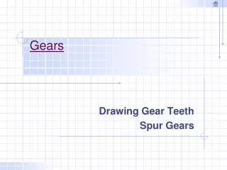
Gears Drawing Bevel Gears
Drawing Bevel Gears Step 1: Calculate the following dimensions: Diameter of the Pitch Circle for the Gear Addendum (0.125) Dedendum (0.1446) Diameter of the Pitch Circle for the Pinion Addendum (0.125) Dedendum (0.1446)
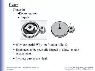
Drawing Bevel Gears Step 2: Draw the pitch cones as shown in the diagram. Draw the main center lines at right angles to each other to intersect at the cone apex (point O). Lay off the pitch diameters of the gear (PA) and the pinion (PB). Draw the lines OA, OP, and OB with form the pitch cone.
Drawing Bevel Gears Step 3: Draw the addendum and the dedendum as shown in the diagram. Draw lines at A, P, and B perpendicular to OA, OP, and OB. Lay off the addendum and dedendum distances and draw light lines to intersect at point O.
Drawing Bevel Gears Step 4: Lay off the face width for both the gear and the pinion, measuring along the pitch cone.
Drawing Bevel Gears Step 5: Calculate the values for the proportions for the remaining features for both the gear and the pinion. Complete the full section view as shown.
Drawing Bevel Gears Step 6: Normally a section view of the bevel gear is all that is required unless a second view is required to show such details as spokes. Establish the position for the center of the circular view. Lay off the main center lines. Project points 1, 2, 3, and 4 from the front view to the circular and draw light circles. Step 7: Lay off the radial center lines for each tooth. The tooth spacing equals 360 degrees / N. An arc whose radius is taken on the back cone is used as the pitch circle and a tooth is developed using standard spur gear formulas. Tooth sizes taken on the OD and pitch diameter are transferred to the front view, and the profiles for the teeth are drawn. Radial lines from these points are taken and the small end of the tooth is developed. Step 8: The teeth on the side or section view can new be drawn by projecting from the front view.