Download
1 / 19
340 likes | 2.42k Vues
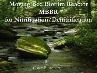
Moving Bed Biofilm Reactor MBBR for Nitrification/Denitrification. By Corey Bjornberg. Nitrogen Sources. Natural Decomposition of Organics Non-point Sources (fertilizers) Point Sources 1) Industry 2) Wastewater. Negative Impacts of Nitrogen on the Environment.

E N D
Moving Bed Biofilm ReactorMBBRfor Nitrification/Denitrification By Corey Bjornberg
Nitrogen Sources • Natural Decomposition of Organics • Non-point Sources (fertilizers) • Point Sources 1) Industry 2) Wastewater
Negative Impacts of Nitrogen on the Environment • Increased levels of nitrate in water supplies can increase the acidity of the water and make toxic metals such as mercury more soluble Nitrate in drinking water can cause Blue Baby Syndrome • Growth of nuisance algae blooms can cause decreased water quality and cause fish kills
Two Step Biological Process Nitrification • Aerobic Autotrophic Bacteria (Nitrosomonas) (Nitrobacter) • Note these are documented as dominate bacteria but others exist in each step
Denitrification • Anaerobic Conditions • Heterotrophic and Autotrophic Bacteria • Nitrite or Nitrate is electron acceptor • Carbon Source Required (Methanol) Nitrate Nitrite Nitric Oxide Nitrous Oxide Nitrogen Gas
Moving Bed Biofilm Reactor Activated Sludge MBBR Trickling Filter
Advantages of MBBR • Smaller Footprint • Utilize whole tank volume for biomass • Less Sludge Produced (Better Settling) • No Return Activated Sludge • Easy Expansion (more media) • No Media Clogging • Reliability and Ease of Operation • Easy to Retrofit Existing Basins
Design Example Outline • Nitrogen Removal • Tertiary Treatment • Nitrification • Denitrification • Municipal Wastewater Goals • Ammonia-N<5 mg/L • Nitrate-N<5 mg/L • Total N<15 mg/L
Basic Design Carbon Source (Methanol) Nitrification Denitrification Influent Effluent Media Fill Media Fill Alkalinity Aeration Mechanical Mixing
Design Parameters • Primary Clarifier Effluent used as Basin Influent • Typical Values Taken From Moorhead WWTF • Process Design for 20ºC • Steady State Conditions • Completely Mixed Reactor • Kaldnes Parameters
Nitrification Tank Design • Nitrification rate of 1 gNH4+-N/m2d (Kaldnes) • Decided on 30% Fill • Resultant SA of 150 m2/m • Ammonia-N Load of 1250 lb/d • Reactor Volume of 130,000 ft3 • Depth of 12 ft • Length to Width 2:1 used • HRT 3.9 hrs Media Design and Characteristics -7 mm Long and 10 mm Diameter -Density of 0.96 g/cm3 -Surface Area of 500 m2/m3 -Typical Fill of 30-50%
Aeration Requirements • Course Bubble Diffusers used to Suspend Media and Oxygen Requirements • Oxygen Transfer Rate of 1%/ft depth Results in 11% Oxygen Transfer Rate (Kaldnes) • Based on earlier stoichiometry • 4.6 gO2/gNH4+-N (Nitrification) • Ammonia Loading used to determine • 110 kgO2/hr • Standard Oxygen Transfer Rate Determined • Air Flow Rate then Determined 4000ft3/min • Diffuser Grid Pattern Design
Alkalinity Requirements Stoichiometry NH4++2HCO3-+2O2→NO3-+2CO2+3H2O • 7.14 g Alkalinity as CaCO3/g N is required • Design Considerations • Assumed Influent Alkalinity of 120 mg/L as CaCO3 • Desired Effluent Alkalinity of 80 mg/L as CaCO3 • Alkalinity Required used for Nitrification is 164 mg/L as CaCO3 • Alkalinity Addition Needed is 124 mg/L as CaCO3 • Total Alkalinity Required 6,200 lbs/d • Strictly Based on Stoichiometry (Further Investigation Needed)
Denitrification Tank Design • Denitrification rate of 2 gNH4+-N/m2d (Kaldnes) • Decided on 30% Fill • Resultant SA of 150 m2/m • Nitrate-N Load of 1,050 lb/d • Reactor Volume of 56,000 ft3 • Depth of 12 ft (Kaldnes) • Length to Width 2:1 used • HRT 1.7 hrs Media Design and Characteristics -7 mm Long and 10 mm Diameter -Density of 0.96 g/cm3 -Surface Area of 500 m2/m3 -Typical Fill of 30-50% Mechanical Mixing
Methanol (CH3OH) Requirements • Carbon Source for Denitrification • Typical dose of 3.2 kg of methanol/kg NO3-N (Metcalf & Eddy) • Based on Nitrate-N Loading of 480 kg/d • Dose of 510 gal/d of Methanol Required
Resultant Design Carbon Source (Methanol) 510 gal/d Nitrification Denitrification HRT=3.9 hrs Volume of 130,000 ft3 Influent HRT=1.7 hrs Volume of 56,000 ft3 Effluent Media Fill (30%) Media Fill (30%) Alkalinity 6200 lbs/d Aeration 4000 ft3/min Mechanical Mixing
Biowin Modeling Biowin Schematic (Steady State) Biowin Results For Nitrification/Denitrification Goals accomplished (NH4+-N, NO3--N<5mg/L, Total N<15 mg/L)
Other Considerations • Simultaneous Removal of Carbon and Nitrogen • Sedimentation Tank due to Increased Solids • More Detailed Design for Alkalinity • Ability to Utilize Existing Infrastructure • Variable Temperature, Flow, and Loading Conditions
Thank You! Questions???