Download
1 / 15
160 likes | 708 Vues
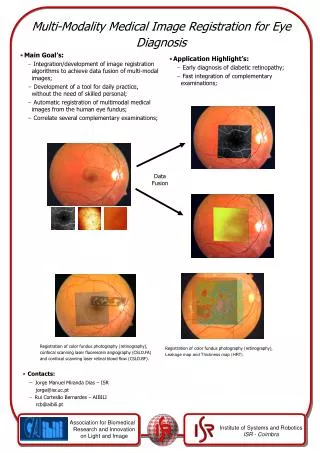
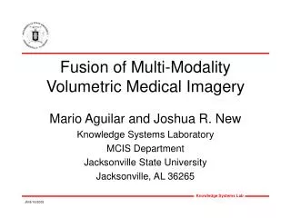
Fusion of Multi-Modality Volumetric Medical Imagery Mario Aguilar and Joshua R. New Knowledge Systems Laboratory MCIS Department Jacksonville State University Jacksonville, AL 36265 Outline What is the neurophysiological motivation of the fusion architecture?

E N D
Fusion of Multi-Modality Volumetric Medical Imagery Mario Aguilar and Joshua R. New Knowledge Systems Laboratory MCIS Department Jacksonville State University Jacksonville, AL 36265
Outline • What is the neurophysiological motivation of the fusion architecture? • How is fusion extended to a three-dimensional operator? • How is this operator applied to volumetric data sets? • What are the results?
GAD PD Color Fuse Result SPECT T2 2D Image Fusion Example
- + 2D Shunt Operator Symbol 3D Shunt Operator Symbol Extensions to 3D Where: A – decay rate B – maximum activation level (set to 1) D – minimum activation level (set to 1) IC – excitatory input IS – lateral inhibitory input C, Gc and Gs are as follows: Where: A – decay rate B – maximum activation level (set to 1) D – minimum activation level (set to 1) IC – excitatory input IS – lateral inhibitory input C and Gs are as follows: 2D Fusion 3D Fusion
T1 Images Color Remap T2 Images Color Fuse Result 3D Fusion Architecture R G B Noise cleaning & registration if needed Contrast Enhancement Between-band Fusion and Decorrelation
3D Shunt Results Original 2D Shunt 3D Shunt
GAD PD SPECT T2 3D Image Fusion Example
3D Fusion Results • 3D Explorer Views – 3D vs. 2D shunt
Conclusions • Development of the 3D shunting operator is a natural extension of the 2D operator • Application of the 3D shunting operator provides better definition of image details in volumetric data sets • 3D fusion extensions developed in the context of Med-LIFE, a visualization and pattern recognition tool.
- + 2D Shunt Operator Symbol 3D Shunt Operator Symbol FUSION SYSTEM EXTENSION 2D Fusion 3D Fusion Shunting Neural Network Equation: Shunting Neural Network Equation: Where: A – decay rate B – maximum activation level (set to 1) D – minimum activation level (set to 1) IC – excitatory input IS – lateral inhibitory input C, Gc and Gs are as follows: Where: A – decay rate B – maximum activation level (set to 1) D – minimum activation level (set to 1) IC – excitatory input IS – lateral inhibitory input C and Gs are as follows:
Results Original 2D Shunt 3D Shunt
Acknowledgements This work was supported by a Faculty Research Grant awarded to the first author by the faculty research committee and Jacksonville State University. Opinions, interpretations, and conclusions are those of the authors and not necessarily endorsed by the committee or Jacksonville State University. For additional information, please visithttp://ksl.jsu.edu.