Download

1 / 18
190 likes | 535 Vues
500 TPD Nitric Acid Plant. 500 TPD Nitric Acid Plant. 17A Marlen Drive w Hamilton, NJ 08691 w USA Tel: (609) 586-8004 w Fax: (609) 586-0002 www.ippe.com. Please click on our logo or any link in this presentation to be redirected to our website, email or other documentation. Thank You!.

E N D
500 TPDNitric Acid Plant 500 TPDNitric Acid Plant 17A Marlen DrivewHamilton, NJ 08691wUSATel: (609) 586-8004wFax: (609) 586-0002www.ippe.com Please click on our logo or any link in this presentation to be redirected to our website, email or other documentation. Thank You!
General Overview Capacity:500 TPD Shut Down: January 2006 Design: C&I Girdler Concentration: 64%-67% NOx Emission: 180 PPM
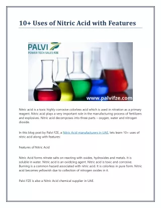
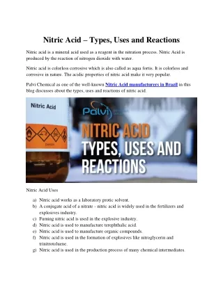
General Overview Key Points • This facility has been producing 65% strength nitric acid since 1971 • The production of nitric acid is a continuous process and the plant produces about 170,000 tons per year • The manufactured Nitric Acid is constantly circulated in a 2,000 ton storage tank before loading tank trucks for delivery • Nitric acid is used in a variety of applications from fertilizer to explosives, as well as a raw material used in the manufacture of other chemical products • There are a complete set of Spare Rotors for the Compressor • New Tailgas Heaters (Never Installed) • Zirconium Tube Bundle Cooler Condenser Purpose The purpose of the nitric acid unit is to produce 65% strength nitric acid from raw materials and a catalyst for use in a variety of applications.
Materials and Products Materials and Products • The production of nitric acid requires only four materials: ammonia, air, platinum and water • Anhydrous ammonia (NH3) and oxygen from the air (O2) is mixed, passed through and reacted with a platinum catalyst gauze to form NOx, then absorbed with H2O to form basic nitric acid • The ammonia is heated to a gas and the gas is then superheated and transferred to the mixer • Air is taken in through the compressor and transferred to the mixer • This ammonia/air mixture is forced through the platinum gauze in the converter • This new gas then enters the absorber column where it is absorbed with water to form basic nitric acid
Manufacturing Process Unit Sections Manufacturing Process Unit Diagram
Manufacturing Process Unit Sections Ammonia Section • The Ammonia Section contains a storage tank from which the anhydrous ammonia is transferred to the vaporizer, superheater and filters
Manufacturing Process Unit Sections Process Air Section • The Process Air Section contains the Steam Turbine, Vera Compressor (filter, silencer, compressor case 1, air cooler and compressor case 2), Expander and Process Air Filter for the required compressed air
Manufacturing Process Unit Sections Product Process Section • The Product Process Section contains the following: • MixerWhere ammonia gas and compressed air mix • ConverterWhere the mixed gases react with a platinum catalyst within the converter • Waste Heat Exchanger & Platinum Filter The mixed gases continue through the waste heat exchanger, then through the platinum filter • Tail Gas Heater, Boiler Feedwater Heaters and Cooler Condenser Used to cool the process stream after passing through the platinum filter • Absorption ColumnThe process stream then enters the absorption column, where nitric acid is formed • Acid HeaterThe acid is heated to make the bleaching process more efficient • Bleacher ColumnThe acid enters the bleacher column where it is bleached to a clear color • Product Acid CoolerThe acid is then cooled in the product acid cooler, which promotes less fumes and decreased corrosion in the storage area. • Product Platinum FilterPrior to the storage area, the acid passes through the product platinum filter • Storage Area
Manufacturing Process Unit Sections Product Process Section Diagram
Manufacturing Process Unit Sections Tailgas Treatment Section • The Tailgas Treatment Section contains the components to eliminate unconverted gases (nitric oxide) that were not absorbed in the absorption column. The components in this section include: • The mist eliminatorRemoves any liquid acid from the tailgas stream • Bleach Air CoolerCools air from the air compressor • Tailgas Heater Reheats the tailgas before it enters the fume abater • Fume Abater Destroys and eliminates nitric oxides in the tailgas • ExpanderUses the hot gases from the fume abater to drive the compressor 2nd stage • EconomizerUses its heat to heat and send water to the boiler • StackVents the cleaned gas to the atmosphere
Manufacturing Process Unit Sections Tailgas Treatment Section
Manufacturing Process Unit Sections Process Utility Section • The Process Utility Section includes hydrogen, butane, instrument air, demin water, cooling tower water and equipment components that are used to produce their own steam and heating/cooling from the heat made by the nitric acid process to continue the process in a complete cycle • When running at mid to full rates, the nitric acid unit produces more thermal utility than it uses. The components include the steam header, surface condenser, steam traps, heat exchangers and demin water supply • The deaerator receives steam and water from the above components where it is heated and transferred to the ammonia superheater • The heated water flows to the ammonia vaporizer, boiler feedwater heaters A&B and to the acid heater • The vestibule jacket is a boiler around the converter • The waste heat exchanger is a boiler in line with the process stream • Water is heated to steam and transferred to the turbine; the excess is exported to plant utilities
Process Flow Process Flow Path • Ammonia from the storage tanks is transferred to the ammonia vaporizer through a magnetic filter, to the ammonia superheater through filters and into the mixer • Air is drawn through an intake filter and silencer to the first case compressor • The air is cooled by the air intercooler and enters the second case compressor then through a process filter and into the mixer • Air and ammonia mix enter the converter where it passes through a platinum/rhodium gauze which forms nitrogen oxide • As it passes through the waste heat exchanger, nitrogen dioxides are also formed • This process gas passes through a platinum filter for platinum recovery • The gas then passes through the tailgas heater, cooler condenser and boiler feedwater heaters for process cooling and enters the absorption column • The nitric oxide is oxidized to form nitrogen dioxide • Water is introduced into the column where it absorbs the nitrogen dioxides to form nitric acid • The acid enters the acid heater where it is heated to make the bleaching process more efficient • The acid enters the bleacher column where it is bleached to a clear color • The acid is then cooled in the product acid cooler. This promotes less fumes and decreased corrosion in the storage area. Prior to the storage area the acid passes through the product platinum filter
Process Flow Process Flow Diagram