MECONTROL Systems MECONTROL Air
340 likes | 764 Vues
MECONTROL Systems MECONTROL Air. Presentation. Our Target: Reliable Drift Free Measurement with low maintenance, high accuracy. MECON TROL Air. Steam generator. Air preheater. Burner. Primary air. Secondary air. Electric precipitator . Flue gas. Coal bunker. Pulverized. fuel.

MECONTROL Systems MECONTROL Air
E N D
Presentation Transcript
Presentation Our Target: Reliable Drift Free Measurement with low maintenance, high accuracy
MECONTROL Air Steam generator Air preheater Burner Primary air Secondary air Electric precipitator Flue gas Coal bunker Pulverized fuel Intermed. Fly-ash bunker Fly ash Excess Air Coal mill FD-Fans System Application for Boiler Optimization
Issues with Air Flow Measurement Calibration? Linearity? Drift (Jamming)? Accuracy in short pipe sections? Flow straighteners (delta P loss)?
Signal Sensor 1 Air Duct or Pipe “Signature” Signal Sensor 2 Sensor 2 Sensor 1 X(t) Y(t)=X(t-T) S=const. T=-26 ms Optimum of correlation “Correlation” correlation Time T Example S=54 cm T=26 ms w=20,8 m/s (average velocity of the air !) MECONTROL AirMeasurement Principle „velocity“
Air duct Measurement cabinet Sensor box (per burner) max. 4 Sensors/2 channels Sensor 1 4 x Sensor signals Sensor 2 Power supply 24 VAC Sensor 3/4 230 VDC Power supply Connection to the DCS MECONTROL AirInstallation overview
Sensor Mounting Adapter Approx 1.5”
Local Sensor Box • 2 Channel Capability • 16” x 12” • Mounted within 50 feet of sensors • Signal Amplification • NEMA 4 Rated • Located within 1000’ of Control Cabinet
Control Cabinet • 48 Channel Capability • 63” x 24” x 79” • 4, 8, 16 & 32 Channel also available • Error Indicators • NEMA 4 Rated • Data Communication: • Modem, FTP, PROFIBUS, MODBUS, Others upon request • 40-80˚ F Temp Required
Single Air Flow Sensor LocationNiederaussem Station, Germany Single Channel 2 sensors (antennas)
Multiple Air Flow Sensor LocationsNiederaussem Station, Germany 3 channels
PS Iskenderun, Turkey: Main plant data: (2 x 600 MW), erected 2003/2004 24 burners, double wall fired: Measurement of: -windbox secondary air system, -core air system with short duct runs, -primary dirty air per burner.
Damper Burner 33 Burner 34 Burner 32 Burner 35 Burner 31 Burner 36 Challenges: - short inlet sections of secondary air - downstream flap dampers - air stratification in ducts
Measuring core air into the burners: Challenges: extremely short measurement sections
Core air duct work: Installation of MECONTROL Air measurement: main core air duct individual burner core air
Individual core air flow position Air flow balance: for proof of plausibility plant demanded a balance to be made of main duct measurements versus indi- vidual core air measurement at each burner.
Measurement of primary air out of the pulverizer measurement of dirty air flow in indivual burner lines subtraction of steam.
Final result of measurement: the secondary air windbox causes main air imbalance 31 32 33 34 35 36
Main Cabinet 230 VAC Conne Power ction supply to the DCS Coal mill at Vattenfall Europe: Power Station Reuter West/Berlin Actual data from: September 2005 Pulverized Pulverized Primary Primary Air Air Fuel Fuel Main Cabinet Main Cabinet Mill Mill 30 30 230 VAC 230 VAC Conne Conne Power Power Reference: Mr. Thorsten Thimme ction ction supply supply to the to the DCS DCS
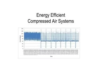
Individual Air flows out of the mill at standardized T and P
Track Record Since 2001: Over 200 installed Never calibrated Never cleaned Temperatures up to 2000o F
MECONTROL Air References • Schwenk Zementwerk in Bernburg 2002measurement of 13 Air flows including Tertiary Air at 1100°C • Vattenfall/BEWAG KW Reuter West Unit D, Berlin 2003Replacement of all 32 conventional Venturi measurements, boiler safety relevant certification (AK3, SIL1) by TÜV Berlin • Vattenfall/BEWAG KW Reuter West Unit E, Berlin 2003Replacement of all 32 conventional Venturi measurements, boiler safety relevant certification (AK3, SIL1) by TÜV Berlin • RWE/Rheinbraun KW Niederaußem Unit G,Bergh.2003 Retrofit of 48 measurement locations including primary and secondary air flows
RWE/Rheinbraun KW Niederaußem Unit A,Bergh.2004 Retrofit of 32 measurement locations including primary and secondary air flows • RWE/Rheinbraun KW Niederaußem Unit E,Bergh.2004 Retrofit of 32 measurement locations including primary and secondary air flows • HOLCIM Texas, Midlothian, 2005 Retrofit of 8 Measurement locations including raw gas and tertiary air • Reliant Energy Niles Power Station, 2006 Measurement of 4 locations on the flue gas side • Thyssen Krupp Steel, Werk Duisburg, 2006 7 measurement locations downstream of steel converter
Southern Company 2005 Retrofit of exhaust gas measurement at 1000 oC and 25 bar pressure in refractory lined coal gasifier • Ashgrove Cement Utah, 2005 Measurement of 8 locations, raw gas as well as tertiary air • Dayton Power and Light, 2006 Retrofit of 8 mills with primary air flow measurement • Vattenfall Kraftwerk Jänschwalde, Unit D2, 2005 Retrofit of 16 measurement locations including primary and secondary air on a ventilation mill by ALSTOM for mill balancing and intelligent control. • EVN Kraftwerk Dürnrohr 2004, Retrofit of 32 burner pipes with velocity measurement for better primary air control.
Steag/Isken Power Station Iskenderun, 2005 16 Measurements of secondary air as well as 6 measurements of coal flow and primary air for better Air balancing • EDF, Power Station West Burton, 2005 16 measurements for measuring OFA of a reburn system (Installed by General Electric) • TXU, Power Station Monticello USA, 2 Units 2006 2 x 10 Measurements for primary air flow. • E2 Power Station Stigsnaes, DK, 2006 12 Measurements for measurement of OFA installed by General Electric
RWE Kraftwerk Niederaußem, Unit H, 2006, measurement of 40 locations secondary as well as primary air flow • Vattenfall Kraftwerk Reuter West Unit D, 2006, measurement of 4x PA before as well as 16x PA after the pulverizer • Vattenfall Kraftwerk Reuter West Unit E, 2006, measurement of 4x PA before as well as 16x PA after the pulverizer