Download
1 / 6
60 likes | 70 Vues
There are different families of products on the market: instruments which measure a single electrical parameter (voltage, current, frequency, and phase angle cosu03d5), generally used in single-phase systems, as instrumentation on the machine, and instruments allowing all the electrical parameters to be measured and displayed, both for the single-phase system and for the three-phase system

E N D
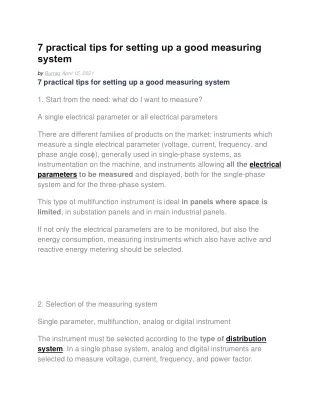
7 practical tips for setting up a good measuring system by Burraq April 15, 2021 7 practical tips for setting up a good measuring system 1. Start from the need: what do I want to measure? A single electrical parameter or all electrical parameters There are different families of products on the market: instruments which measure a single electrical parameter (voltage, current, frequency, and phase angle cosϕ), generally used in single-phase systems, as instrumentation on the machine, and instruments allowing all the electrical parameters to be measured and displayed, both for the single-phase system and for the three-phase system. This type of multifunction instrument is ideal in panels where space is limited, in substation panels and in main industrial panels. If not only the electrical parameters are to be monitored, but also the energy consumption, measuring instruments which also have active and reactive energy metering should be selected. 2. Selection of the measuring system Single parameter, multifunction, analog or digital instrument The instrument must be selected according to the type of distribution system. In a single phase system, analog and digital instruments are selected to measure voltage, current, frequency, and power factor.
In a three-phase system, instruments can be installed that measure the single electrical parameter, one per phase, or a voltmeter and a current can be installed with the voltage and current switches, allowing the measurements to be displayed in sequence. , phase by phase. Choosing an analog instrument ensures good reading stability, due to the mechanical inertia of the needle and the fact that the reader immediately knows whether the instrument is operating normally or if the reading is out of range. The analog instrument indicates the point of the measurement scale on which it is located, indicating the upper and lower limits. Moving coil counters (photo credit: directindustry.com) In digital instruments, this indication is not. The only possible reference is the reading of the displayed value, for example, of the current. Some measuring instruments have bar indicators that show the current level as a percentage of the set full scale. Choosing a digital instrument guarantees better readability, also in low light conditions, especially for instruments with LED displays, and immediate reaction to measurement variation. 3. System sizing, choice of CT
The sizing of the measurement system begins with knowing the main parameters of the plant; in particular, from the characteristics of the protection switch, the type of distribution system, the rated current, the rated voltage and the type of busbar can be known. Current transformers used in measuring equipment for 400A three-phase power supply (photo credit: Wikipedia) After having defined the type of instrument best suited to the needs, if the measurement is performed by indirect insertion, the accessories of the measuring system, such as current and voltage transformers must be chosen with care. If 800 A Current is to be measured, in most cases the instrument cannot be connected directly to the line. A current transformer suitable for the application must therefore be selected. The parameters chosen for a current transformer are not only the rated current, the secondary current and the power, but also the type of assembly. Flexible and rigid cables or bars for power transport can be installed in a power panel. Transformers can be of different types, depending on the assembly system: a through cable or a cable with a coiled primary, transformers for assembly on horizontal or vertical bars. 4. Wiring and wiring diagrams
Connecting analog instruments is very simple; you just need to connect the phase and neutral cables to the instrument. Two auxiliary power cables should always be connected for digital instruments. Multifunctional instruments can be used in different distribution systems. In three-phase systems with distributed neutral three current transformers are required. In three-phase systems without distributed neutral in which the loads are balanced and symmetrical, an insertion can be made, i.e. two current transformers instead of three can be used; the instrument will calculate by difference the third phase which is not measured directly, considering it as identical to the other two. In multifunction instruments, not only the cables connected to the measurement, but also the RS485 serial port and the analog and digital inputs and outputs must be wired. 5. Instrument and earthing protection In order to ensure that the instrument is properly protected, fuses must always be fitted to the power cables of the digital instruments and to the measurement inputs of the voltmeter. Earthing of CT secondary's ensures earthing if the transformer has a fault and does not affect the measurement. If there is a large potential difference between neutral and earth, this could negatively affect the measurement, in the case of instruments with non-galvanically isolated measurement inputs.
6. Adjustment of digital instruments Before digital instruments begin to operate, they must be set with measurement system parameters and communication parameters. The main measurement parameters are the transformation ratios of CTs and VTs, which are defined as the mathematical relationship between the nominal value and the secondary value; For example, setting the transformation ratio of a CT3 / 100 scanner with a secondary at 5 A means setting kCT = 100: 5 = 20 7. Troubleshooting during final testing The main problems that arise during the testing phase can be due to incorrect installation of instruments and accessories. Always check that the wiring conforms to the instruction manual. Errors during installation The following errors are the most common mistakes when installing a measuring instrument: •Reverse CT secondary's •Invert the phases of the current and voltage measurement inputs •No elimination of the CT secondary's short-circuit •Setting an incorrect transformer ratio.
Burraq Engineering Solutions is providing practically electrical courses in Lahore. We offer PLC course, SOLAR SYSTEM Installation and DESIGN COURSE, ETAP course, DIALAX course, Panel FABRICATION course, VFD course, ADVANCED Course Panel, SWITCHERGEAR design course, Building Electrical design course and all electrical diploma courses in Lahore.