Download
1 / 38
420 likes | 780 Vues
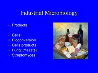
Industrial Microbiology INDM 4005 Lecture 3 11/02/04. SECTION 2:. 2. UNIT OPERATIONS Overview: Asepsis Media Inocula Delivery systems. 2.1. ASEPSIS. Application of directed changes to an environment to prevent or retard the growth of contaminating organisms.

E N D
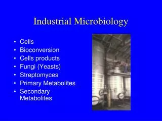
SECTION 2: 2. UNIT OPERATIONS Overview: Asepsis Media Inocula Delivery systems
2.1. ASEPSIS • Application of directed changes to an environment to prevent or retard the growth of contaminating organisms. • Fundamental to GOOD INDUSTRIAL LARGE SCALE PRACTICE (GILSP) when applying GMP to a biotech process.
AIM • Protect system • Protect operator and environment • Relate degree of asepsis to cost\ potential hazard
ASEPSIS (1)OPTIONS - Asepsis related to level and type of microorganisms present = BIOBURDEN Eliminate; 1. in raw materials 2. at each stage of process 3. at end of process (2) METHOD • Sterilisation, • Disinfection, • Pasteurisation etc.
(3) TECHNIQUES • Heat e.g. autoclave • Filtration e.g. heat-labile liquid, air • Physical e.g. irradiation • Chemical e.g. Caustic soda, ethanol etc. • Design e.g. laminar air-flow (LAF units)
2.1.1. MANAGEMENT - ASEPSIS • Design of plant - flow through isolated departments; Raw materials in --> stage 1 --> stage 2 --> product --> out Personnel - clothing, health, hygiene Process equipment design - • e.g fermenter design --> asepsis Design of ancillary equipment and services; • Inoculation • Media preparation • Finishing operations e.g. Pasteurisation, aseptic packaging etc. Design of treatment/ sterilisation cycle e.g. temp. and duration
Management of asepsis --> Quality Assurance Function CASE STUDY Devise a protocol required for QA Factory Hygiene. Identify major microbiological tests to monitor level of cleanliness in a factory.
2.1.2. REACTOR DESIGN AND ASEPSIS 1. Vessel material --> steam sterilisation 2. Entry / exit points / ports - threaded covers, sterilisable 3. Pipework - eliminate pockets, dead spaces, designed slopes 4. Valves - pinch / diaphragm best 5. Impeller glands / bearings require special seals 6. Gas inlet - filter input supply, non-return valves 7. Gas outlet - filter (protect environment), prevent back-flow 8. Sterilise additives e.g. antifoam, acid/alkali etc. 9. Aseptic sampling - sequence to sterilise with steam, cool, collect and re-sterilise 10. Transfer of inoculum - sequence + valves etc. Above principles incorporated into the design of sterile operating / processing facilities - See additional sheet
Inoculation of a plant fermenter from another plant fermenter Fermenter Seed Tank C J G F Steam A B D E I H Trap Trap
(a) REACTOR / EQUIPMENT DESIGN 1. Moving metal (e.g. rotor shaft with impeller) in contact with fixed metal (e.g lid of fermenter) = problem to eliminate contamination. REQUIRE SEALS. 2. The satisfactory sealing of the stirrer shaft assembly is essential to maintain asepsis in long fermentation runs. 3. A simple stirrer seal is shown below Stirrer shaft Top bearing Yoke Fermenter top plate Skirt Bottom bearing
TYPES OF SEALS • Packed-gland seal The impeller shaft is sealed with several layers of packing rings of asbestos or cotton yarn At high speeds the packing can wear away Difficult to sterilise • Bush seals Composed of a stationary seal and a rotating seal Common in laboratory scale fermenters • Mechanical seals Commonly used in large fermenters Seal is composed of two parts, one stationary the other rotating, with the two components forced together with springs • Magnetic seals
Reactor Design and asepsis 2. Valves are required to control the flow of liquid e.g. transfer of inoculum from seed to production tank. A wide range of valve types exist TYPES OF VALVE suitable for sterile uses; Pinch valve (Close valve by tightening a flexible sleeve with pinch bars operated by compressed air remotely or automatically) Diaphragm (Also uses flexible closure, failure due to excessive handling) Ball (Consists of stainless steel ball, with a machined hollow centre, can operate under high pressure) Safety valves incorporated into air / steam lines - ensure that pressure does not exceed specification
TYPES of PUMPS • Used to transport liquids or gases; 1. Centrifugal - fan type, impeller imparts velocity to stream of fluid. Often lacks force 2. Rotary - positive displacement with circular motion. Scoops the fluid from pump chamber. Often used as source of power e.g. hydraulic systems 3. Reciprocating - to and fro motion PROBLEMS; Rotary /reciprocating - compression heat (problems with temp. control due to aeration in fermenter) Contamination (e.g. Oil) may present difficulty. Leakage Property of liquid; Caustic soda corrosive, rubber-lined centrifugal pump Viscosity - e.g. keep molasses warm
TYPES of PUMPS ASEPTIC PUMPING OF LIQUIDS; Difficult to sterilise mechanical pump. Leakage problems overcome by Diaphragm pump (fig 8.10) PERISTALTIC PUMP - compress pliable tubing between rollers, forces liquid through the tube Pump mechanism and liquid are never in contact
CASE STUDY Draw different types of seals, valves and pumps, comment on design of pipework and asepsis
(b) STERILIZATION OF AIR USING FILTERS; (1) TYPES • PORE SIZE SMALLER THAN PARTICLES - absolute • PORE SIZE GREATER THAN PARTICLES - fibrous Mechanisms of fibrous filters include; • Inertial impaction • Interception • Diffusion • Electrostatic attraction Can be influenced by air velocity. Problem if wet (condensation)
(2) EFFICIENCY Given by ratio of the number of particles removed (N) to that present originally (N0 ) Plot of ln N / N0 against filter length (x) will yield a line of slope K K is influenced by filter material and by linear velocity of air passing through the filter This gives the basis of calculating the required length and diameter of filter to give a specified level of protection (or contamination) ....... see chapter 5.
Asepsis • All fermentation equipment must be kept scrupulously clean and sanitized to avoid contamination by microorganisms. • Good cleaning and sanitation has become especially necessary with the growing use of non-pasteurized products and the reduced use of additives. • Cleaning and sanitizing may be separate or combined processes.
Cleaning Detergents • Detergent must have the capacity to break the soil into fine particles and to hold them in suspension so that they do not redeposit on the cleaned surface. • Detergents also must have good sequestering power to keep calcium and magnesium salts (causes beerstone in brewing process) in solution. • There are two types of cleaning detergents: alkaline or acid that are often formulated with surfactants, chelating agents, and emulsifiers to enhance the effectiveness of the detergents. • The most effective detergents in the use today are formulated with alkaline solutions that have chelators and surfactants.
Sanitizing Agents • The objective in sanitizing is to reduce the number of microorganisms present on a surface to acceptable levels. • This is done with steam treatment or chemical sanitizers- alkaline and acid disinfectants.
Cleaning And Sanitation Manual • First step in any effective cleaning and sanitation program is the development of a detailed, up-to-date manual. • This manual should establish a systematic procedure for cleaning each major piece of fermenter equipment, listing the frequency, method, and materials to be used for cleaning. • For each cleaning procedure discussed in the manual, the weight or volume of material used should be given relative to the amount of water used, along with the concentrations of each material involved. • The manual also should include the schedule of routine microbiological assessments or surveys to evaluate the sanitary conditions and, hence, the effectiveness of the cleaning and sanitizing operation.
Material And Corrosion Resistance • Stainless Steel • The corrosion inhibitor in stainless steel is the passive oxide layer that protects the surface. • Beerstone (calcium oxalate) can cause corrosion if not removed, because the metal beneath the deposit becomes oxygen-depleted. • Many types of stainless steel exist. The type of stainless steel used in fermentation equipment is the nonmagnetic 300 series.
Material And Corrosion Resistance • Copper • Copper generally is more acid-resistant than alkaline-resistant. • Copper is usually resistant to non-oxidizing acids such as acetic, hydrochloric, and phosphoric, but is not resistant to oxidizing acids such as nitric and sulfuric nor to non-oxidizing acid solutions that have oxygen dissolved in them. • Alkaline detergents will blacken copper due to the formation of oxides. • Commercial detergents usually contain buffering agents and inhibitors that prevent corrosion of copper.
Material And Corrosion Resistance • Aluminum • Caustic cleaners react with aluminum, actually dissolving the metal and pitting the surface. • The reaction with aluminum can produce a potentially dangerous situation, in that flammable hydrogen gas is produced. • Proper ventilation is necessary under these conditions. • The unsightly pitting that can occur can be a good harboring point for bacteria.
Methods Of Application Manually Small production outlets do not have the luxury of cleaning-in-place systems and have to manually clean and sanitize their equipment. The choice and concentration of detergents is limited in manual applications, given the risks to the user. In addition, the temperature of the water is usually limited between 48 and 50ºC. Clean-in-Place Systems Clean-in-place (CIP) systems were developed by the dairy industry. The simpler CIP units are usually made of at least one stainless steel tank, a centrifugal supply pump, stainless steel valves, a steam injection line, and tank spraying devices.
What Is CIP (Cleaning In Place) • CIP widely used in all types of process industries. • CIP main purpose is to remove solids and bacteria from vessels and pipework in the food and drinks processing industries. • CIP allows process plant and pipework to be cleaned between process runs without dismantling equipment. • It can be carried out with automated or manual systems and is a reliable and repeatable process that meets the stringent hygiene regulations especially prevalent in the food, drink and pharmaceutical industries.
Benefits Of Cleaning In Place Safety • Production down time between product runs is minimised• Cleaning costs can be reduced substantially by recycling cleaning solutions• Water consumption is reduced as cleaning cycles are designed to use the optimum quantity of water• The cleaning system can be fully automated therefore reducing labour requirements• Automated CIP systems can give guaranteed and repeatable quality assurance• Automated CIP systems can provide full data logging for quality assurance requirements• Hazardous cleaning materials do not need to be handled by operators• Use of cleaning materials is more effectively controlled using a CIP system
CLEANING IN PLACE SYSTEMS • A CIP system can be an automated, sequenced system with the option of manual intervention or a semi-automatic system. • All process equipment are provided with in-built cleaning systems to facilitate thorough cleaning.
Process Control & Automation • Fermentation is a critical bioprocess and hence it is essential to monitor each and every step. The control of Cleaning In Place systems can vary from simple manual operation to fully integrated Programmable Logic Controller (PLC) controls with touch screen operator interfaces. • Level 1: To control critical process parameters and maintain consistency in product quality. • Level 2: PLC based Control System with Data Acquisition facility to control critical process parameters and log data. • Level 3: PLC based control system with auto sequencing and data acquisition system. This system facilitates control of critical process parameters, fault Logging and with a provision of generating reports with an option of internet based remote access.
Different Types Of CIP Systems Single Pass systems In a single pass system new cleaning solution is introduced to the plant to be cleaned and then disposed to drain. In most cases a single pass system would start with a pre-rinse to remove as much soiling as possible. The detergent clean and a final rinse would follow this.
Recirculation systemCleaning solution is made up in an external tank, introduced to the plant to be cleaned, recirculated and topped up as required until the cleaning cycle is complete. In general recirculation systems use less water & cleaning detergents but require greater capital outlay.
System Design • The first design consideration for a Cleaning In Place system is the cleaning requirement for each process vessel. • Factors to be considered can include • the size of the process vessels; • standard of cleaning required, • the available cleaning time, • the type of cleaning medium, • and whether recycled detergent can be used.With this information cleaning heads can be selected to meet the requirements described above. This then allows pumps to be selected to match the flow rates required for the heads and the type of cleaning material being used. • The module size and configuration can also be calculated from this information.
System Design • The process diagram on next slide shows an example of a three-tank Cleaning In Place system. • There are three holding tanks, which are mounted in a stainless steel bund. • The tanks are normally a bulk caustic tank, dilute detergent tank and fresh water tank. • Bulk cleaning liquid is normally delivered to a connection point outside the process plant and pumped to the storage tank by the delivery vehicle. • Heating can be specified for the bulk cleaning liquid tank depending on the properties of the cleaning agent. • Lagging and cladding can also be fitted for improved energy efficiency.
The bulk cleaning liquid is pumped to the detergent tank before each cleaning cycle along with water to make up a batch of detergent. • The detergent is normally more effective at a higher temperature. If this is the case it would then be pumped through a plate heat exchanger to bring it to the required temperature. • The system shown below allows the detergent to be re-circulated through the heat exchanger until it reaches the optimum temperature.
CASE STUDY • DESIGN A CIP SYSTEM FOR BREWING. • Compare various chemical agents. • See textbooks on Brewing
Summary • Bioreactor design and asepsis • Design of sterile operating and processing facilities • Importance of CIP • Levels of CIP systems • Process control