Download
1 / 23
230 likes | 526 Vues
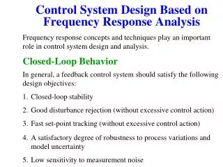
The FSM model of a Control System: practical information. The finite state machine model of a DCS (FSM DCS) allows for the user to automatically operate the detector (not simply monitoring!!) according to a predefined sequence of actions via a graphic user interface (GUI).

E N D
The FSM model of a Control System:practical information The finite state machine model of a DCS (FSM DCS) allows for the user to automatically operate the detector (not simply monitoring!!) according to a predefined sequence of actions via a graphic user interface (GUI). In addition it allows for partitioning and integration of the FSM DCS in the ALICE CS. An example given will show how to build it. G. De Cataldo CERN-CH, A. Franco INFN Bari, I
The Device Oriented Control System To get the FSM DCS it has proven effective to follow these steps: • Once the detector’s subsystems have been defined (HV, LV, Gas, Cooling,…..) then the integrationin PVSS of the related devices (PS, Board, channel) should be done via the JCOP Framework (FW) editor/navigator panel (an application running in PVSS). This operation will result in the Device Oriented Control System that contains simple monitoring and operation features. Since now this will be referred as the DeviceO CS which is mirrored in a well defined PVSS data points structure (Dp). G. De Cataldo CERN-CH, A. Franco INFN Bari, I
e.g.: the present HMPID CS Hardware Win2000 WS running Step7 for PLC prog. development Win2000 DCS Workstation with JCOP FW(PVSS), CAEN and Siemens OPC’s… Ethernet CAEN SY1527 CAEN A1676W WIENER PL500F8 PLC Some actuators ( as Liq. circ. Sub -system) CANbus Physical Parameters HV Sub-system LV Sub-system G. De Cataldo CERN-CH, A. Franco INFN Bari, I
Device definition in the FW: e.g. SY1527, A1821P and A1676W CAEN boards Device oriented hierarchy The A1821P is a 12 ch HV board to provide about 2KV to the HMPID MWPC, while the A1676W is a branch controller that allows for to control up to eight WIENER PL500F8 fully equipped with 64 channels. So the A1676W appear to be a CAEN board with 64 channel, then compatible with the CAEN OPC server! New Dps are defined for the A1676W board as well as its new simbol in the CAEN board library G. De Cataldo CERN-CH, A. Franco INFN Bari, I
Channel Definition on the A1676W Board in the FW 1.2 This is a modified panel (by A. Franco, HMPID) for the WienerPS configuration provided by S. Popescu in the FW1.2 G. De Cataldo CERN-CH, A. Franco INFN Bari, I
LV Channel Monitoring and simple operation for the A1676W board in fw 1.2 This is a modified panel (by A. Franco, HMPID) for the WienerPS configuration provided by S. Popescu in the FW1.2 G. De Cataldo CERN-CH, A. Franco INFN Bari, I
The Detector Oriented Control System • According to the physicist experience a Detector oriented CS, provides a more effective detector monitoring and operation. In order to build this DetectorO CS, • first of all the detector has to be represented by means of minimal independent parts (e.g. modules, sectors…) that, as the case may be, they can be operated independently providing useful data for the analysis. G. De Cataldo CERN-CH, A. Franco INFN Bari, I
Detector Oriented CS hierarchy • Secondlyvia the FW, the specific Dps, representing the detector parts, and the related Detector Oriented panels (GUI) should be respectively defined and designed. The panels should be mainly intended for monitoring purposes and all the related monitoring information have to be there presented. G. De Cataldo CERN-CH, A. Franco INFN Bari, I
Monitoring panel of the HMPID LV sub-system G. De Cataldo CERN-CH, A. Franco INFN Bari, I
Linking panel between the DeviceO CS and the DetectorO CS (e.g. FERO sector) This linking panel has been developed ad hoc to establish a connection between LV channels and the HMPID LV Modules. Any failure of one of this channel can be recovered changing the link from the bad channel to a new one. The CS will continue to work perfectly. Link with the FEE/RO Segment List of the available LV channels G. De Cataldo CERN-CH, A. Franco INFN Bari, I
Monitoring/operation panels of one LV Module FEE Negative polarities FEE Positive polarities Setting and operation parameters G. De Cataldo CERN-CH, A. Franco INFN Bari, I
Monitoring panel of the HMPID HV sub-system G. De Cataldo CERN-CH, A. Franco INFN Bari, I
Monitoring/operation panels of one HMPID HV Module Trend panel Single HV channel operation panel G. De Cataldo CERN-CH, A. Franco INFN Bari, I
The FSM CS for automation, integration and partitioning of the DCS • The third step is intended to implement the DCS automation, partitioning and finally its integration in the ALICE CS. All these features can be obtained, at the same time, if a Finite State Machine model of the DCS (FSM DCS) is implemented. This step should be carried out in the SMI++ environment which has its interface in the JCOP FW. In this environment new links between Dps representing detector parts and logical objects, as Control and Device Units (CU, DU), have to be established. All the related documentation can be found starting from : http://clara.home.cern.ch/clara/fw/FSMConfig.pdf G. De Cataldo CERN-CH, A. Franco INFN Bari, I
CU and DU, the basic elements for the FSM DCS The DU and CU are logical objects behaving as a FSM! For both of them can be defined a finite number of states they can assume (ON, OFF, RmUP…), and related commands (GO_ON, GO_OFF, RESET…) to let them to move between the states according to the relevant state diagram that the expert has defined for its detector. For some subsystems (HV and LV) a standardization of the state diagrams is under way. Moreover, the CU (not the DU) can contain a control program (in State Management Language SML) which includes the sequence of operations to be automatically performed once a command has been issued. The resulting behavior arising from the combination of some of these logical objects represents the Finite State Machine model of the DCS (or sub-system CS). G. De Cataldo CERN-CH, A. Franco INFN Bari, I
SMI Control Unit HMPID DCS SMI Device Unit HVPS1 PLC S300 Hardware Device e.g.: Control & Device Units in the HMPID CS Architecture Working in progress This CU and DU architecture, mirrors the Detector Oriented CS Advanced Status External to the HMPID CS HMPID DCS HV LV LCS COOL GAS Phis. Par Cooling System Gas System HVMod 1 LVSctr 1 LCSMod 1 HVPS1 LVPS1 LCSMain LVPS1 CAEN SY1527 HV PS PLC S300 PLC S300 WIENER PL500F8 LV PS G. De Cataldo CERN-CH, A. Franco INFN Bari, I
Config. Panel for Device Type Working with the SMI++ toolkit Config. Panel for Logical Object type Configuring Hierarchy of FSM G. De Cataldo CERN-CH, A. Franco INFN Bari, I
FSM Device Units FSM Device Units FSM Device Units FSM DP FSM DP FSM DP HVm1 HVm1 HVm1 HV Channels A Flexible and tailored interface between the hardware and HVmodule • At present, in order to get a FSM DCS Detector Oriented, the best compromise is to combine the features of the SMI++ language with the PVSSII script programs. While the first is manly oriented to manage logical states, the second is more powerful. Their combination in the HMPID FSM CS has allowed not only to define the FSM model(SMI++), but also to manage alarm conditions on one or more sectors in one HMPID module, to provide log features to track the user operation while trying to repair the fault condition (PVSSII script). • All the parameters and variables of the CAEN SY1527 Crate are linked, by the OPC server/client, to a set of PVSS DataPoints defined in the Device oriented CS in the Framework. • Eight additional DataPoints are defined as Logical Devices, one for the HV Power Supply and 7 for the HMPID HV Modules, they are the interfaces to the FSM Device Units • For each Device Unit an associated FSM has been defined using the SMI++ Framework tools • An High Voltage Control Unit Domain and the relative SMI++ control program have been created. • A devoted Interface Control Scripts Program (PVSS II) is requested to convert, all the information including the alarm conditions coming from the SY1527, plugged boards and channels, in logical objects (Device Unit) behaving as FSM’s … HV (Control Prog In SML) Interface Script Program (PVSS) Framework device DPs DCOM/OPC connection CAEN SY1527 G. De Cataldo CERN-CH, A. Franco INFN Bari, I
The GUI for the FSM CS For each CU or DU there are related operation panel from where the commands can be issued and the logical state read to operate the corresponding detector or sub-system part. In this panel, those developed for the Detector oriented CS may be included and then recycled! Nothing prevent the definition of a new one. In the final HMPID CS, the combination in one panel of monitoring and operation features has proven to be effective for the detector operation (e.g.during test beam), monitoring, debugging. Of course, some lock mechanism on the detector operation will prevent interference with the Experiment Control System once the detector control will be demanded at that level. G. De Cataldo CERN-CH, A. Franco INFN Bari, I
C6F14 RADIATOR ROL ROR COOLING e.g.: the HMPID GUI operation and monitoring panel G. De Cataldo CERN-CH, A. Franco INFN Bari, I
HV system monitoring and control G. De Cataldo CERN-CH, A. Franco INFN Bari, I
Conclusions • To build a FSM CS the first step is the implementation of the Device Oriented CS in the JCOP FW; • The Second step is to realize the Detector Oriented CS in the JCOP FW; • Finally, profiting of the DeviceO and DetectorO CS, the implementation of the FSM CS in the SMI++ environment to get automation, partitioning and integrating features for your control system. • Suggestion: try to define the minimal parts of which your detector can be made of ( it has to provide useful data for the analysis!) and sketch your Detector Oriented Graphic User Interface. Do not hesitate to contact us for a conversation on the subject. G. De Cataldo CERN-CH, A. Franco INFN Bari, I
The Interface Control Script Program • When the Domain Control Program send an action (command) to a FSM Device Unit, the related DataPoint values change. • This results in the execution of a subroutine that according to the command received modify all the related values in the DataPoint elements. Physical Devices FSM Device Units Event fired by a Request of Action Command to Devices Jasd j i= 0 If(kjsad) asd asda Jkd askd aksd kaksd as Asdas asd 1 CAEN SY1527 crate Primo [FwSy1527] HVpa1 [hmpidHVPS] HV Power Supply 5 CAEN A1821 boards Primo_board01 [FwCaen1527Board] HV Module 1 Primo_board01 [FwCaen1527Board] Primo_board01 [FwCaen1527Board] Primo_board01 [FwCaen1527Board] Primo_board01 [FwCaen1527Board] HV Module 2 Jasd j i= 0 If(kjsad) asd asda Jkd askd aksd kaksd as Asdas asd 49 CAEN HV channels Primo_board01_ch01 [FwCaenChannel] Primo_board01_ch01 [FwCaenChannel] Primo_board01_ch01 [FwCaenChannel] Primo_board01_ch01 [FwCaenChannel] HVm1 [hmpidHVM] HV Module 3 Primo_board01_ch01 [FwCaenChannel] HVm1 [hmpidHVM] Primo_board01_ch01 [FwCaenChannel] HVm1 [hmpidHVM] Primo_board01_ch01 [FwCaenChannel] HVm1 [hmpidHVM] HVm1 [hmpidHVM] HVm1 [hmpidHVM] HVm1 [hmpidHVM] HV Module 4 Changing of the Device Status Event fired by value changing HV Module 5 HV Module 6 • When a parameter value of the Physical Device changes, this variation is propagated into the corresponding DataPoint element value. • This event activate a subroutine that according to new parameter value may bring the corresponding D.U.(HV Module) in a new state. HV Module 7 G. De Cataldo CERN-CH, A. Franco INFN Bari, I