Circuit Board : Electric Gate
Circuit Board : Electric Gate 24V Power supply White # 5-- To red on Gate solenoid Black # 6-- To black on gate solenoid #4 & # 8 loop for buzzer # 3 red – To alert buzzer # 9 Green – To alert buzzer # 13 and # 14 For dry contact activation ( Push Button) # 17 and # 18

Circuit Board : Electric Gate
E N D
Presentation Transcript
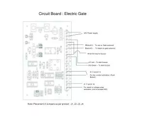
Circuit Board : Electric Gate 24V Power supply White # 5-- To red on Gate solenoid Black # 6-- To black on gate solenoid #4 & # 8 loop for buzzer # 3 red – To alert buzzer # 9 Green – To alert buzzer # 13 and # 14 For dry contact activation ( Push Button) # 17 and # 18 For serial or voltage pulse activation, (not to exceed 24V) Note: Placement of Jumpers as per product : J1, J2, J3, J4
Circuit Board : Lights For Turnstiles and Gate applications 24 Volt power supply # 2 and # 6 To- red light Black and white wire #4 and # 8 loop # 3 and # 9To -green light. Red and Green wire # 13 and # 14 for Dry contact activation ( Push Button) Note: Placement of Jumpers as per product : J1, J2, J3, J4
Circuit Board : Electric Gate with photo eye. 24 Volt power supply # 5 Red wire to- gate solenoid. # 6 Black wire to- gate solenoid # 10 White wire to- Brown wire of photo eye # 11 Black wire to- white wire of photo eye. # 12 Red wire to- black and blue wire of Photo eye # 13 and # 14 for dry contact activation, (If required*) Note: Placement of Jumpers as per product : J1, J2, J3, J4
Circuit board :Waist high Turnstile / High Gate. 24 volt power supply. # 5 White wire to- Turnstile Solenoid # 6 Black wire to- Turnstile Solenoid # 15 Red wire to- Micro switch # 16 Green wire To- Micro switch # 13 and #14 For dry contact activation ( Push Button ) # 17 and # 18 For Serial or Voltage post, ( not to exceed 24volts) Note: Placement of Jumpers as per product : J1, J2, J3, J4
Circuit Board : Magnetic Lock Gate. 24 Volt Power supply # 5 White wire to Red on Gate Magnet # 6 Black wire to Black on Gate magnet # 13 and # 14 For dry contact activation ( Push Button) # 17 and # 18 for serial or voltage pulse activation, ( not to exceed 24 V) Note: Placement of Jumpers as per product : J1, J2, J3, J4
600lbs Magnetic lock specifications. • CX-91M-06 • Installation Instructions • 5502 Timberlea Blvd. • Mississauga, Ontario L4W 2T7 • 905-366-3377 Toll Free: 877-226-3369 • www.camdencontrols.com • ModelDescriptionFeaturesCurrent Draw • CX-91M-06 Single Basic 480mA @ 12V240mA @ 24V • CX-91M-06TDS Single adj. timer, door position switch & bond sensor • SHOCK HAZARD. Care must be taken to keep the power supply and wiring isolated from ground (earth). Use of an ohmmeter to test for shorts is recommended prior to service. • A. 12V DC Input: • Set jumpers for 12V DC operation. (See diagram below) Connect the ground (-) lead from a 12V DC power source to terminal 2.Connect the positive (+) lead from a 12V DC power source to terminal 1. • B. 24V DC Input: • Unit is delivered from Factory with single jumper ON for 24V operation.Connect the ground (-) lead from a 24V DC power source to terminal 2.Connect the positive (+) lead from a 24V DC power source to terminal. • C. Contacts: • Reed switch dry contacts are rated 0.5 Amp@30V DC/AC. For safe operation, do not exceed this rating.If you normally require a normally open contact, connect to the black and green wire of the PCB.If you normally require a normally closed contact, connect to the black and red wire of the PCB. • Printed Circuit Board Schematic • (shown with all options) • Jumper 12V DC 24V DC Magnet Power Selector IC 1 Timer Power Supply Reed Switch (Sensor) White Blue Green Black Red NC NO VR C110 V AC Switch or Solid State Switching Device 12 or 24 VDC CORRECT 110 V AC Switch or Solid State Switching Device 12 or 24 VDC INCORRECT • Important • Power switch should always be wired as shown below in order to minimize the effect of residual magnetism. • Contact Camden for other wiring considerations.
Turnstile Counter Technical Manual 702084-0001 Series C342 Self Powered LCD Display HV Input Introduction Your Veeder-Root brand Series C342 panel instrument is powered by an internal lithium battery, features an 8 digit LCD display and is housed in a ultra compact 1/32 DIN package. An IEC IP65 rated front panel is suitable for washdown environments. All models feature signal and remote-reset inputs capable of accepting the high voltage AC or DC impulses They can be applied in much the same manner as electromechanical devices of similar voltage rating, but have the inherent life and reliability benefits of modern electronic design. This product has been configured at the factory to perform one of the following functions: Count Totalizer, Time Totalizer (Hours:Minutes:Seconds), or Time Totalizer (Hours, 1/100 resolution). Features • Available models include count and time totalization • Unique input circuit accepts 12 to 250 V, AC/DC, for signal and reset functions • Crisp 8 digit LCD display provides easy to read process values • Compact 1/32 DIN bezel and 60mm behind the panel depth save panel space • Internal lithium battery provides long life and eliminates the need for external power • IEC IP65 rated front panel for use in washdown environments Veeder-Root brand S E T U P OPERATION Front Panel Reset Used to reset the Process Value Display, unless disabled through the keylock input
ABB Modular Range of Pilot Devices In addition to traditional operators like Pushbuttons, Selector switches, Emergency stops and Pilot lights, ABB also offers a wide range of special functions such as Machine stops, Toggle switches, Buzzers, Definite purpose pushbuttons, Potentiometers and Reset buttons. The pilot devices have a modern, robust and functional design and can be used both indoor and outdoor. On front side the products meet protection degree IP66 and on terminal side they meet IP20. They are also approved in accordance with UL Type 1, 3R, 4, 4X, 12 and 13. Operators are available with bezels in three different alternatives i.e. black plastic, chrome plastic and metal. Rotation is prevented by ridges and springs on the operators. The Contact blocks are provided with a wiping, cleaning function to secure the contact function. The contact carriers are color coded to indicate normally open and normally closed contacts. For all illuminated products the same lamp blocks can be used for both filament bulbs and LED’s. The operators and pilot lights are fast and easy to install by use of snap-on solutions. Installation of contact blocks and actuators can be done separately and pre-wiring is possible.