Download

1 / 9
0 likes | 2 Vues
Alloy beams and beam like elements are principal constituents of many structures and widely used in high speed machinery,<br>aircraft and light weight structures. Crack is a damage that often occurs on members of structures and may cause serious<br>failures of structures. In this research the natural frequency of a cracked cantilever beam is investigated by finite element<br>method by using of ANSYS program with different crack depth and location effect. The beam material studied is aluminum<br>alloy, titanium alloy, copper alloy and magnesium alloy. A comparison is made between these alloys and conclude

E N D
International Journal of Research in Engineering and Innovation Vol-1, Issue-1 (May-2017), 20-28 ____________________________________________________________________________________________________________________________ International Journal of Research in Engineering and Innovation (IJREI) journal home page: http://www.ijrei.com ISSN (Online): 2456-6934 ___________________________________________________________________________________ Vibration analysis of a cantilever beam with crack depth and crack location effects Husain Mehdi1, Arshad Mehmood2 1Department of Mechanical Engineering, Meerut Institute of Technology, Meerut, India 2Department of Mechanical Engineering, College of Engineering/ University of Buraimi, OMAN ______________________________________________________________________________________________________________ Abstract Alloy beams and beam like elements are principal constituents of many structures and widely used in high speed machinery, aircraft and light weight structures. Crack is a damage that often occurs on members of structures and may cause serious failures of structures. In this research the natural frequency of a cracked cantilever beam is investigated by finite element method by using of ANSYS program with different crack depth and location effect. The beam material studied is aluminum alloy, titanium alloy, copper alloy and magnesium alloy. A comparison is made between these alloys and conclude optimized result between them. The increase of the beam length result in a decrease in the natural frequencies of the composite beam and also shows that an increase of the depth of cracks lead to a decrease in the value of natural frequencies. . Key words: Aluminum Alloy, Copper Alloy, Titanium Alloy, Natural frequency, Mode Shapes __________________________________________________________________________________________________ 1. Introduction All structures are subjected to degenerative effects that may cause initiation of structural defects such as cracks which, as time progresses, lead to the catastrophic failure or breakdown of the structure. Thus, the importance of inspection in the quality assurance of manufactured products is well understood. Cracks or other defects in a structural element influence its dynamical behavior and change its stiffness and damping properties. Consequently, the natural frequencies of the structure contain information about the location and dimensions of the damage [1]. The dynamic response-based damage detection method attracts most attention due to its simplicity for implementation. This technique makes use of the dynamic response of structures which offers unique information on the defects contained with these structures. Changes in the physical properties of the structures due to damage can alter the dynamic response, such as the natural frequency and mode shape. These parameter changes can be extracted to predict damage detection information, such as the presence, location, and severity of damage in a structure. The natural frequency provides the simplest damage detection method since damage tends to reduce the stiffness of the structure. ©2016 ijrei.com. All rights reserved Therefore, a reduction of natural frequency may indicate the existence of damage in the structure. However, the natural frequency is a global feature of the structure, from which the location of the damage is difficult to determine. The modal parameters (e.g., the mode shape and flexibility), which can capture the local perturbation due to damage are used in order to locate damage [2]. A crack may reduce the flexural rigidity of a column and its load carrying capacity .From the reduced flexural rigidity, the deflection and the load carrying capacity of a notched column may be calculated .The bending at the crack section of a column causes a tensile mode crack up stress field, which is characterized by a stress intensity factor. When the stress intensity factor at a crack tip exceeds the fracture toughness of the material, fracture occurs. The fracture toughness of cracked column is studied [3]. In many circumstances material flaws are present in structures made of anisotropic composites .Such cracks can be detected by vibrational analysis based on the variation of the local compliance as the crack gradually grows. The significance of this term on the local flexibility of a centrally cracked plate is discussed by presenting a numerical example for a graphite fiber for a reinforced Corresponding author: Husain Mehdi Email Address: husainmehdi4u@gmail.com 20
Husain Mehdi et al/ International journal of research in engineering and innovation (IJREI), vol 1, issue 1 (May-2017), 20-28 polyamide composite. The prospect of crack diagnosis of composite components on the basis of coupled deformation modes due to the crack presence is signified by analyzing the compliance matrix of a prismatic beam containing a central crack [4]. A crack in a structural element introduces a significant local flexibility which enhances the instability. Buckling of a edge notched beam is studied for isotropic and anisotropic composites. The local compliance due to presence of cracks in anisotropic medium is formulated as a function of crack -tip stress intensity factors and the elastic constants of the material [5]. The equation of motion & associated boundary conditions are derived for a uniform Bernoulli-Euller beam containing one single- edge crack. The main idea is to use a generalized vibrational principle that allows for modified stress, strain, & displacement field that enable one to satisfy the compatibility requirements in the vicinity of the crack [6]. It was investigated a new beam finite element with a single non-propagating one-edge open crack located in its mid-length is formulated for the static & dynamic analysis of cracked composite beam -like structures. The element include two degree of freedom at each of the three nodes, a transverse deflection and an independent rotation respectively [7]. The Eigen frequencies of a cantilever beam, made from graphite fiber reinforced polyamide with a transverse one edge non-propagating open crack are investigated .Two models of beam are presented.in the first model the crack is modelled by a massless substitute spring .The flexibility of the spring is calculated on the basis of fracture mechanics and the castigiliano theorem. The second model is based on the finite element method (FEM) [8]. It was investigated that the presence of a crack in a structural member introduces a local flexibility that effects its vibration response .Moreover the crack will open and close in time depending on the rotation and vibration amplitude .In this case the system is non-linear [9]. The characteristic matrices of a composite beam with single transverse fatigue crack are presented. The element developed has been applied in analyzing influence of the cracked parameters (position and relative depth)and the material parameters relative volume and fiber angle)on changes in the first four transverse natural frequencies of the composite beam made to unidirectional composite material [10]. The dynamics of a fixed-three bar with a breathing crack in longitudinal vibration is investigated .The crack was modelled as a continuous flexibility using the displacement field in the vicinity of the crack found with fracture mechanics methods[11]. It was investigated that a piece-wise linear approach to analyze vibrations of a cantilever beam with a 'breathing crack’. Their formulation was hybrid frequency-domain/time-domain method. For the majority of vibration, the crack section is unambiguously either open or closed [12]. The numerical modelling of damage and crack propagation in concrete and concrete structures has evolved considerably in the past years. In this contribution ,a higher order continuum model is used to model the failure behavior of single -edge notched & double- edge notched concrete beams loaded in four-point shear .The influence of the ratio of the compressive strength & the tensile strength is scrutinized and its relation with the failure mechanism is investigated [13]. It was analyzed that the dynamic behavior of cracked beam, the effect of crack on a structure by comparing the signal in frequency & the time domain: and concluded that ,increase in crack depth results the increase in amplitude of vibration .Secondly the amplitude of low frequency vibration decreases and high frequency vibration increases when the location of crack increases [14]. The modelling methods of structural elements with failures (cracks and delamination) is presented. Cracks appear in both isotropic and anisotropic materials .Delamination is one of the most important failure modes of laminated composite materials. Delamination may originate during manufacturing or may be induced during in -service loading ,such as by foreign object impact or by fatigue common damage in composite materials is matrix- cracking, fiber-breakage ,fiber-matrix debounding [15]. different approaches to crack modelling , and demonstrates that for structural health monitoring using low frequency vibration based on beam elements are adequate .They also addresses the effect of the excitation of breathing cracks, where the beam stiffness is bilinear ,depending upon the whether the beam is open or close [16]. The bending free vibration of cantilevered composite beams weakened by multiple non-propagating part through surface crack is presented .Toward determining the local flexibility characteristics induced by the individual cracks, the concept of massless rotation is applied [17]. 2.Governing Equation 2.1Structure Analysis The differential equation of the bending of a beam with a mid-plane symmetry (Bij = 0) so that there is no bending- stretching coupling and no transverse shear deformation (εxz=0) is given by IS11(?4?/??4) =q(x) It can easily be shown that under these conditions if the beam involves only a one layer, isotropic material, then IS11=EI=Ebh3/12 and for a beam of rectangular cross- section Poisson’s ratio effects are ignored in beam theory, which is in the line with Vinson & Sierakowski (1991). In Equation 1, it is seen that the imposed static load is written as a force per unit length. For dynamic loading, if Alembert’s Principle are used then one can add a term to Equation.1 equal to the product mass and acceleration per unit length. In that case Equation.1 becomes IS11d4?(?,?)/??4=q(x,t)-???2?(?,?)/??2 where ω and q both become functions of time as well as space, and derivatives therefore become partial derivatives, (1) (2) 21
Husain Mehdi et al/ International journal of research in engineering and innovation (IJREI), vol 1, issue 1 (May-2017), 20-28 ρ is the mass density of the beam material, and here F is the beam cross- sectional area. In the above, q(x, t) is now the spatially varying time-dependent forcing function causing the dynamic response, and could be anything from a harmonic oscillation to an intense one-time impact. For a composite beam in which different lamina have differing mass densities, then in the above equations use, for a beam of rectangular cross-section ?? = ??ℎ = ∑ ??(ℎ ?=1 However, natural frequencies for the beam occur as functions of the material properties and the geometry and hence are not affected by the forcing functions; therefore, for this study let q(x,t) be zero. Thus, the natural vibration equation of a mid-plane symmetrical composite beam is given by IS11[d4?(?,?)/??4]+??[?2?(?,?)/??2]=0 It is handy to know the natural frequencies of beams for various practical boundary conditions In order to insure that no recurring forcing functions are close to any of the natural frequencies, because that would result almost certainly in a structural failure. In each case below, the natural frequency in radians /unit time is given as ?n=?2√(??11/???4) Where α2 is the co-efficient, which value is catalogued by Warburton, Young and Felgar and once ωn is known then the natural frequency in cycles per second (Hertz) is given by fn= ωn/2π, which is in the line with Vinson & Sierakowski (1991). In general, governing equation for free vibration of the beam can be expressed as [K]-?2[M]{q}=0 Where, K = Stiffness matrix M = Mass matrix , and q = degrees of freedom. 2.2Modal Analysis (Mehdi. H et al [24]) 2.2.1 Damping Matrices Damping may be introduced into a transient, harmonic, or damped modal analysis as well as a response spectrum. The type of damping allowed depends on the analysis as described in the subsequent sections. Transient (Full or Reduced) Analysis and Damped Modal Analysis: The damping matrix, [C], may be used in transient and damped modal analyses as well as substructure generation. In its most general form, the damping matrix is composed of the following components. N N N 2 2 1 ma m e k [M] E m m [C] ( g)[K] [M ] [( g g )[K ]] [C ] i j i j j j k 1 1 1 i j N N 1[C g v m Where [C] = structure damping matrix, α = mass matrix multiplier, [M] = structure mass matrix, β = stiffness matrix multiplier, [K] = structure stiffness matrix, Nma = number of materials, αim = mass matrix multiplier for material I, [Mi] = portion of structure mass matrix based on material I, Nmb = number m j = stiffness matrix multiplier for material j, [Kj] = portion of structure stiffness matrix based on material j, Ne = number of elements with specified damping, , [Ck] = element damping matrix, Ng = number of elements with Coriolis or gyroscopic damping, [Gl] = element Coriolis or gyroscopic damping matrix Harmonic (Full or Reduced) Analysis: The damping matrix ([C]) used in harmonic analyses is composed of the following components. 2 [M] ( g)[K] [C ] i ] [G ] m l 1 1 l (7) ? k-hk-1) (3) of materials, (4) N N 2 1 ma m E m m [M ] [( g g )[K ]] i j i j j j 1 1 j N N N 1 g e v k m [C ] [C ] [G ] k m l 1 1 1 l The input exciting frequency, Ω, is defined in the range between ΩBand ΩE via ΩB= 2πfB, ΩE= 2πfE fB = beginning frequency fE = end frequency Substituting equation (8) into the harmonic response equation of motion and rearranging terms yields j j j [[K] 2 [K] (2g g )[K ] [K ] [C ] [G ]]](u j j j iu (8) (5) [ [M] [K] E m [C ] [M ] i g i m i i 2 m ) F [M] (6) k 1 2 1 (9) The complex stiffness matrix in the first row of the equation consists of the normal stiffness matrix augmented by the structural damping terms given by g, gi, giE, and [Cm] which produce an imaginary contribution. Structural damping is independent of the forcing frequency, Ω, and produces a damping force proportional to displacement (or strain). The terms g, gi, and giE are damping ratios (i.e., the ratio between actual damping and critical damping, not to be confused with modal damping). The second row consists of the usual viscous damping terms and is linearly dependent on the forcing frequency, Ω, and produces forces proportional to velocity. 22
Husain Mehdi et al/ International journal of research in engineering and innovation (IJREI), vol 1, issue 1 (May-2017), 20-28 2.2.2 alloy, Mg-alloy, Ti-alloy and Cu-alloy, like ultimate tensile strength, yielding strength. In these alloys titanium alloy has a greater ultimate strength than the other alloys, whereas magnesium alloy has a lower ultimate strength. These mechanical properties are fed into ANSYS-14.0 to calculate the natural frequency for alloy cantilever beam. Table 1: Properties of Selected Materials Mode-Superposition Analysis The damping matrix is not explicitly computed, but rather the damping is defined directly in terms of a damping ratio ξd. The damping ratio is the ratio between actual damping i d and critical damping. The damping ratio the combination of Where ξ = constant modal damping ratio, ratio for mode shape i (see below), ωi = circular natural frequency associated with mode shape i = 2πfi, fi = natural frequency associated with mode shape I, α = mass matrix multiplier The modal damping ratio mode directly (undamped modal analyses only). Alternatively, for the case where multiple materials are present whose damping ratios are different, an effective mode-dependent damping ratio modal analysis if material-dependent damping is defined and the element results are calculated. This effective damping ratio is computed from the ratio of the strain energy in each material in each mode using N m s j j j m i N s j j for mode i is d m (10) Tensile Ultimate Strength Mpa i i i 2 2 Tensile Yield Strength Mpa i Density Kg/m3 Material i m = modal damping Mg- Alloy Al- Alloy Cu- Alloy 1800 2770 8300 193 280 280 255 310 430 Ti- Alloy 4620 930 1070 i m can be defined for each 930 1000 STRENGTH (MPA) TENSILE YIELD 800 i m can be defined in the 600 280 280 400 193 200 0 Mg- Alloy Al- AlloyCu- Alloy Ti- Alloy m E MATERIAL 1 m E (a) (11) 1 1200 ULTIMATE TENSILE 1000 STRENGTH (MPA) 800 Where Nm = number of materials, material j 1( ) [K ]( ) 2 Strain Energy contained in mode i for material j, {φi} = displacement vector for mode I, [Kj] = stiffness matrix of part of structure of material j These mode-dependent ratios ,?? superposition or spectrum analysis. Note that any manually- defined damping ratios will overwrite those computed in the modal analysis via equation-11 3.Results and Discussions In order to check the natural frequency of cantilever alloy beam, first we calculate the mechanical properties of Al- 600 m = damping ratio for j 400 200 0 T s Mg- Alloy Al- AlloyCu- Alloy Ti- Alloy E j j i MATERIAL (b) (and material-dependent) Figure 1: comparison of Mechanical properties (a) tensile yield strength, (b) Ultimate tensile strength ?will be carried over into the subsequent mode- 23
Husain Mehdi et al/ International journal of research in engineering and innovation (IJREI), vol 1, issue 1 (May-2017), 20-28 Table 2: Comparison of Natural Frequency with and without crack at 50 mm crack location 50mm crack location Natural Frequency (Hz) Mode Shape crack 1 23.656 23.176 2 93.849 93.136 Cu Alloy 3 147.97 4 413.25 5 503.77 6 571.19 1 32.503 2 128.91 Mg Alloy 3 203.3 4 567.79 5 689.43 6 784.5 1 29.644 2 117.55 Ti Alloy 3 185.41 4 517.85 5 626.32 6 715.21 1 32.887 2 130.7 Al Alloy 3 205.7 4 574.49 5 703.12 6 794.37 Table 3: Comparison of Natural Frequency with and without crack at 100 mm crack location Alloy Alloy 100mm crack location Natural Frequency (Hz) Mode Shape crack 1 23.656 2 93.849 3 147.97 4 413.25 5 503.77 6 571.19 1 32.503 2 128.91 3 203.3 4 567.79 5 689.43 6 784.5 1 29.644 2 117.55 3 185.41 4 517.85 5 626.32 6 715.21 1 32.887 2 130.7 3 205.7 4 574.49 5 703.12 6 794.37 without 2mm crack depth 4mm crack depth 21.59 90.233 134.86 376.32 487.58 549.03 29.675 123.95 185.37 517.26 667.3 754.08 27.075 113.02 169.13 471.96 606.24 687.51 30.005 125.47 187.42 522.96 680.49 763.53 without 2mm crack depth 23.466 93.573 146.63 409.23 504.62 569.27 32.243 128.54 201.48 562.3 690.6 781.87 29.408 117.2 183.76 512.88 627.39 712.82 32.621 130.11 203.84 568.88 704.31 790.169 4mm crack depth 22.729 92.317 138.87 390.112 498.01 556.93 31.233 126.81 190.86 536.16 681.57 764.36 28.491 115.63 174.12 489.4 619.19 696.86 31.592 128.37 193.01 542.2 695.07 773.97 Cu Alloy Mg Alloy Ti Alloy Al Alloy 144.84 404.53 500.35 566.72 31.846 127.94 199.02 555.87 684.76 778.38 29.048 116.66 181.53 507.04 622.08 709.65 32.217 129.5 201.33 562.32 698.35 788.13 24
Husain Mehdi et al/ International journal of research in engineering and innovation (IJREI), vol 1, issue 1 (May-2017), 20-28 Table 5: Comparison of Natural frequency for without crack Natural Frequency Without Crack Mode Shape Alloy Alloy 1 23.656 32.503 2 93.849 128.91 3 147.97 203.3 4 413.25 567.79 5 503.77 689.43 6 571.19 784.5 Table 6: Comparison of Natural Frequency with different crack location at 2 mm crack depth Table 4: Comparison of Natural Frequency with and without crack at 150 mm crack location 150mm crack location Natural Frequency (Hz) Copper Mg Ti Al 2mm crack depth 23.554 93.713 147.09 409.89 503.67 569.99 32.363 128.73 202.11 563.19 689.3 782.4 29.517 117.38 184.33 513.68 626.2 713.7 32.744 130.31 204.48 569.8 702.98 792.69 4mm crack depth 23.234 93.23 143.63 398.27 502.53 564.46 31.925 128.07 197.37 547.32 687.74 775.27 29.119 116.77 180.04 499.28 624.79 706.81 32.297 129.64 199.64 553.56 701.38 785 Alloy 29.644 32.887 117.55 185.41 517.85 574.49 626.32 703.12 715.21 794.37 Alloy Mode Shape 1 2 3 4 5 6 1 2 3 4 5 6 1 2 3 4 5 6 1 2 3 4 5 6 without crack 23.656 93.849 147.97 413.25 503.77 571.19 32.503 128.91 203.3 567.79 689.43 784.5 29.644 117.55 185.41 517.85 626.32 715.21 32.887 130.7 205.7 574.49 703.12 794.37 Cu Alloy Mg Alloy Ti Alloy Al Alloy 130.7 205.7 Crack location 2mm crack depth Natural Frequency (Hz) Mode Shape Alloy 1 23.176 31.846 2 93.136 127.94 3 144.84 199.02 4 404.53 555.87 5 500.35 684.76 6 566.72 778.38 1 23.466 32.243 2 93.573 128.54 3 146.63 201.48 4 409.23 5 504.62 6 569.27 781.87 1 23.554 32.363 2 93.713 128.73 3 147.09 202.11 4 409.89 563.19 5 503.67 6 569.99 Cu Mg Alloy Ti Al 50mm 100mm 150mm Alloy 29.048 116.66 181.53 507.04 622.08 709.65 29.408 117.2 183.76 512.88 627.39 712.82 29.517 117.38 184.33 513.68 626.2 713.7 Alloy 32.217 129.5 201.33 562.32 698.35 788.13 32.621 130.11 203.84 568.88 704.31 790.169 32.744 130.31 204.48 569.8 702.98 792.69 562.3 690.6 689.3 782.4 It can be seen that in every mode shape Cu Alloy has minimum natural frequency while Al Alloy has maximum natural frequency. To reduce these natural frequencies cracks are introduced in different location with different crack depth and we analyzed that at 50 mm crack location with 4mm crack depth natural frequency has a minimum value for all alloys. 25
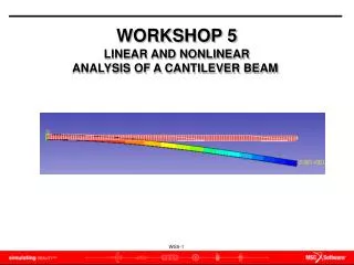
Husain Mehdi et al/ International journal of research in engineering and innovation (IJREI), vol 1, issue 1 (May-2017), 20-28 Now when frequency of alloys are compared with no crack and with 9 cracks then It has been observed that frequency decreases with number of cracks. Table 7: Comparison of Natural Frequency with different crack location at 4 mm crack depth Crack 4mm crack depth location Natural Frequency Mode Shape Alloy 1 21.59 2 90.233 50mm 3 134.86 4 376.32 5 487.58 6 549.03 1 22.729 2 92.317 100mm 3 138.87 4 390.112 5 498.01 6 556.93 1 23.234 2 93.23 150mm 3 143.63 4 398.27 5 502.53 6 564.46 3.1Natural frequencies for various mode shapes The modal analysis of the alloy beam is done on ANSYS 14. The following are the different mode shapes to produce natural frequency in composite beam Figure 3 Second mode of vibration Cu Mg Alloy 29.675 123.95 185.37 517.26 667.3 754.08 31.233 126.81 190.86 536.16 681.57 764.36 31.925 128.07 197.37 547.32 687.74 775.27 Ti Al Alloy 27.075 113.02 169.13 471.96 606.24 687.51 28.491 115.63 174.12 489.4 619.19 696.86 29.119 116.77 180.04 499.28 624.79 706.81 Alloy 30.005 125.47 187.42 522.96 680.49 763.53 31.592 128.37 193.01 542.2 695.07 773.97 32.297 129.64 199.64 553.56 701.38 785 Figure 4 Third mode of vibration Figure 5 Forth mode of vibration Figure 6 Fifth mode of vibration Figure 7 Sixth mode of vibration The first mode of vibration is a bending mode In this mode shape, the beam is tending to bend about the root section’s The analysis shows that the parameter that effect root stiffness have a large impact on the first mode of frequency. The first mode frequency is also affected by parameters that effect tip mass. The second mode of vibration is also a bending mode and the natural frequency of second mode of vibration is greater than the first mode of vibration. The third mode of vibration is also bending mode with one node formation about the root, the frequency is more than Figure 2 First mode of vibration 26
Husain Mehdi et al/ International journal of research in engineering and innovation (IJREI), vol 1, issue 1 (May-2017), 20-28 the second mode .the deflection was in the vertical direction. The frequency is correspondingly higher due to increased stiffness in that direction. The fourth mode of vibration is also bending mode with two node formation. The frequency of fourth mode shape is much higher than the above three modes. The fifth mode of vibration is twisting about the root, the frequency is affected by tip rotational moment of inertia. The frequency of sixth mode shape have the highest frequency in all the above mode shapes. Mode 1: When the force is applied at right angles to the surface of beam. Mode 2: When the force is applied vertically & horizontally on beam. Mode 3: Node formation during free vibrations due to forces at right angle to surface. Mode 4: Two node formation during free vibrations of the beam. Mode 5: Twisting of beam by fixing one end Mode 6: Natural vibration of the composite beam under transverse loading i.e. force acting along the width of beam. 4.Conclusion The mechanical properties of aluminum alloy, magnesium alloy, titanium alloy and copper alloy were found by using computational method. From the above results, following conclusions can be made Table 1 shows the comparison between the mechanical properties like tensile yield strength, tensile ultimate strength of all four alloys. From Figure-1 it can be concluded that the tensile strength of Ti alloy is highest amongst all alloys taken and has a minimum deflection comparison to all alloy The natural frequency decreases with increasing crack depth. From table 2-7 it has been observed that natural frequency decreases when number of cracks increases. References [1]Krawczuk M., and Ostachowicz W.M., (1995). “Modeling and Vibration analysis of a Cantilever composite beam with a transverse open crack”. Journal of Sound and Vibration183(1), 69-89. [2]Ramanamurthy (2008). “Damage detection in composite beam using numerical modal analysis”. International Journal on Design and Manufacturing Technologies, Vol.2, No.1. [3]Hiroyuki Okamura, H.W Liu & Chorng -Shin Chu 'A Cracked Column under Compression’ Engineering Fracture Mechanics Vol.1, 1969. [4]Nikpour K, Dimarogonous A.D, ' Local compliance of Composite Cracked Bodies 'Compos Sci Techno 1988; 209-223. [5]Nikpour K. 'Buckling of Cracked Composite Columns Int J Solids Struct 1990; 26 (12):1376-86. [6]Mo-How H-Shen ' Natural Modes of Bernaulli-Euler Beams with a Single Edge Crack ' American Institute of Aeronautics & Astronautics, AIAA, 1990. [7]Krawczuk M.A new finite element for the fbeams, Comput Struct 1994; 52(3):551-61. [8]Krawzcuk M, Ostachowicz W.M. 'Modelling & vibration analysis of a Cantilever Composite Beam with a transverse open crack J sound Vib 1995;69-89. [9]Dimarogonous A.D. 'Vibration cracked structure a state of the art review ' Engineering Fract Mech 1996; 55(5); 831-57. [10]Krawczuk M,Ostachowicz W .' AModal Analysis of Cracked Unidirectional Composite Beam ‘Compos part B 1997;28:641-50. [11]T.G Chrondus ,A.D.Dimarogonous & J Yao 'Longitudinal vibration of a bar with breathing crack' Engineering Fracture Mechanics Vol.61,1998. [12]Kisa .M. & Brandon ,J.A.' The effect of closure of cracks on the dynamics of a cracked cantilever beam ' Journal of Sound & Vibration 2000; 238(1),1-18. [13]M.G.D. Geers ,R de Borst & R.H.J Peerings ' Damage & crack modelling in single -edge beams' Engineering Fracture Mechanics ,Vol.65,2000. [14]T.G.Chrondus ,A.D. Dimarogonous & J Yao' vibration of a beam with a breathing crack 'Journal of sound & Vibration vol.239 NO.1,2001. [15]Ostachowicz W. & Krawczuk M. 'On Modelling of structural stiffness loss due to damage' DAMAS 2001: 4TH International Conference on Damage Assessment of Structures ,Cardiff; pp.185-199. [16]M.I.Friswell & J.E.T. Penny 'crack modelling for structural health monitoring 148,2002. [17]Song O , Ha TW ,Librescu L. 'Dynamics of anisotropic composite cantilevers weakened by multiple tranverse open cracks ' Engineering Fract Mech 2003;70;105-23. [18]Murat Kisa ,'Free Vibration Analysis of a Cantilever Composite Beam with Multiple Cracks Composites Science & Technology,VOL.64;2004. [19]T.T.Lu, H.Y Hu & Z.C Li ' Highly accurate solutions of Mortz & cracked beam problems 'Engineering analysis with boundary elements ,vol.28;2004. [20]Ertugal Cam Sadettin Orhan & Murat Luy 'An analysis of cracked beam structure using impact echo method 'NDT&E International ,vol.38,2005. [21]K.El Bikri ,R.Benamar “Geometrically non-linear free vibrations of clamped - clamped beams with an edge crack computers & structures” ,vol.84,pp.485-502,2006. [22]Saber El-Arem & Habiboumaitoumam'Acracked beam finite element for rotating shaft dynamics & stability analysis journal of mechanics of materials & structures ,vol.3,No.5;2008. vol.1,No2,pp.139- &M.M.Bennouna 27
Husain Mehdi et al/ International journal of research in engineering and innovation (IJREI), vol 1, issue 1 (May-2017), 20-28 [23]Luay S. Al-Ansari ,Muhannad Al-Waily & Ali-Hajjar 'Experimental & Numerical study of crack effect on frequency of simpy supported beam 'Al Khawarizmi Engineering journal vol.8.no2,2012. [24]Husain Mehdi, Rajan Upadhyay, Rohan Mehra, Adit Singhal, “Modal Analysis of Composite Beam Reinforced by Aluminium-Synthetic Fibers with and without Multiple Cracks Using ANSYS” International Journal of Mechanical Engineering, vol. 4 issue 2, pp 70-80. 28