Download
1 / 9
90 likes | 104 Vues
"ITEM: RT/57220/M/160<br>Saves 20% space over the basic length of a corresponding ISO/VDMA cylinder<br>Low friction, long life seals<br>High strength, double crimped end cap design<br>Standard magnetic piston for full control system versatility"<br>For More Information visit on our website:- www.instronline.com<br>Our E-mail Address:-info@instronline.com <br>

E N D
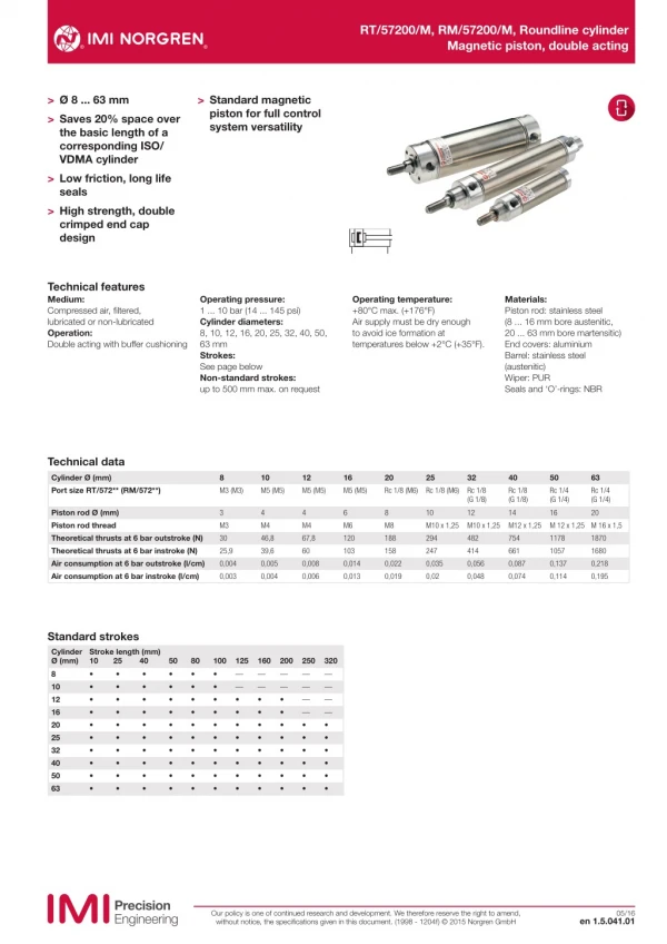
RT/57200/M, RM/57200/M, Roundline cylinder Magnetic piston, double acting > Ø 8 ... 63 mm > Saves 20% space over the basic length of a corresponding ISO/ VDMA cylinder > Low friction, long life seals > High strength, double crimped end cap design > Standard magnetic piston for full control system versatility Technical features Medium: Compressed air, filtered, lubricated or non-lubricated Operation: Double acting with buffer cushioning Operating pressure: 1 ... 10 bar (14 ... 145 psi) Cylinder diameters: 8, 10, 12, 16, 20, 25, 32, 40, 50, 63 mm Strokes: See page below Non-standard strokes: up to 500 mm max. on request Operating temperature: +80°C max. (+176°F) Air supply must be dry enough to avoid ice formation at temperatures below +2°C (+35°F). Materials: Piston rod: stainless steel (8 ... 16 mm bore austenitic, 20 ... 63 mm bore martensitic) End covers: aluminium Barrel: stainless steel (austenitic) Wiper: PUR Seals and ‘O’-rings: NBR Technical data Cylinder Ø (mm) Port size RT/572** (RM/572**) 8 M3 (M3) 10 M5 (M5) 12 M5 (M5) 16 M5 (M5) 20 Rc 1/8 (M6) 25 Rc 1/8 (M6) 32 Rc 1/8 (G 1/8) 40 Rc 1/8 (G 1/8) 50 Rc 1/4 (G 1/4) 63 Rc 1/4 (G 1/4) Piston rod Ø (mm) Piston rod thread Theoretical thrusts at 6 bar outstroke (N) Theoretical thrusts at 6 bar instroke (N) Air consumption at 6 bar outstroke (l/cm) Air consumption at 6 bar instroke (l/cm) 3 M3 30 25,9 0,004 0,003 4 M4 46,8 39,6 0,005 0,004 4 M4 67,8 60 0,008 0,006 6 M6 120 103 0,014 0,013 8 M8 188 158 0,022 0,019 10 M10 x 1,25 294 247 0,035 0,02 12 M10 x 1,25 482 414 0,056 0,048 14 M12 x 1,25 754 661 0,087 0,074 16 M 12 x 1,25 M 16 x 1,5 1178 1057 0,137 0,114 20 1870 1680 0,218 0,195 Standard strokes Cylinder Ø (mm) 10 25 40 8 • 10 • 12 • 16 • 20 • 25 • 32 • 40 • 50 • 63 • Stroke length (mm) 50 • • • • • • • • • • 80 • • • • • • • • • • 100 • • • • • • • • • • 125 160 200 250 320 • • • • • • • • • • • • • • • • • • • • — — • • • • • • • • — — • • • • • • • • — — • • • • • • • • — — — — • • • • • • — — — — • • • • • • Our policy is one of continued research and development. We therefore reserve the right to amend, without notice, the specifications given in this document. (1998 - 1204f) © 2015 Norgren GmbH 05/16 en 1.5.041.01
RT/57200/M, RM/57200/M, Roundline cylinder Magnetic piston, double acting Cylinder variants Model magnetic piston Description Dimensions Symbol Page R./57200/M Standard cylinder, Ø 8 to 40 mm, integral eye mounting, Ø 50 and 63 mm 4 & 5 R./57200/MC R./57200/MF R./57200/JM Cylinder with central rear port Cylinder with flat rear cover Cylinder with double ended piston rod (Ø 16 to 63 mm) 5 5 4 Option selector R˙/572˙˙/˙˙/˙˙˙ Port size Cylinder Ø (mm) 8 10 12 16 20 20 25 25 32 32 40 40 50 50 63 63 Substitute Stroke (mm) 500 max. Cylinder variants Magnetic piston Magnetic piston, central rear port, flat end T T T T M T M T M T M T M T M T M3 M5 M5 M5 M6 Rc1/8 M6 Rc1/8 G1/8 Rc1/8 G1/8 Rc1/8 G 1/4 Rc 1/4 G 1/4 Rc 1/4 Substitute M MC MF Magnetic piston, side port, flat end JM Magnetic piston, double ended piston rod Cylinder Ø (mm) 8 10 12 16 20 25 32 40 50 63 Substitute 08 10 12 16 20 25 32 40 50 63 Our policy is one of continued research and development. We therefore reserve the right to amend, without notice, the specifications given in this document. (1998 - 1204f) © 2015 Norgren GmbH en 1.5.041.02 05/16
RT/57200/M, RM/57200/M, Roundline cylinder Magnetic piston, double acting Mountings Ø 8 ... 40 mm 3 5 12 15 11 Ø 50 and 63 mm 1 3 9 8 6 11 7 14 1 3 9 8 7 14 AK C F H L N Cyl. 1 2 3 4 5 6 7 8 9 10 8 9 9 10 3 4 5 6 7 8 9 10 18 11 12 13 14 15 Page 7 10 16 17 19 20 1 8 2 9 3 10 4 5 6 7 10 1 2 3 4 5 Page 6 20 QM/57008/24 QM/947 QM/947 QM/946 QM/8012/24 QM/57025/24 QM/8020/24 QM/57040/24 QM/57050/24 QM/57063/24 6 7 8 9 Page 6 Page 6 Page 6 Page 6 Ø 16 11 17 11 12 18 12 13 — QM/8010/38 QM/8010/38 QM/8012/38 QM/8020/38 QM/8025/38 QM/8025/38 QM/8040/38 QM/8040/38 QM/8050/38 19 13 14 20 14 15 15 16 M/P71273/1 M/P71273/2 M/P71273/2 M/P19369 M/P19389 M/P40381 M/P19406 M/P71273/3 QM/57050/21 QM/57063/21 16 17 17 18 18 19 QM/57008/25 QM/8010/25 QM/8010/25 QM/57016/25 QM/57020/25 QM/57025/25 QM/57032/25 QM/57040/25 QM/57040/25 QM/57063/25 19 20 13 11 14 12 15 13 16 14 21 17 15 22 18 16 23 19 17 24 M/P71364 M/P71364 M/P71364 M/P1501/90 M/P13834 M/P13607 M/P13615 M/P29254 — — 20 18 25 19 20 26 27 28 29 20 11 12 13 14 15 11 — — — — — — — — QM/55240/28 QM/55250/28 12 8 25 20 26 20 21 10 12 16 20 25 32 40 50 63 27 21 22 28 22 23 29 23 24 24 25 25 26 26 27 27 28 28 29 22 20 23 21 24 22 30 25 23 31 26 24 32 27 25 33 28 26 34 29 27 35 28 29 29 20 21 22 23 24 20 21 36 37 38 39 35 30 36 30 31 37 31 32 38 32 33 39 33 34 34 35 35 36 36 37 37 38 38 39 32 30 33 31 34 32 35 33 36 34 37 35 38 36 39 37 38 39 30 30 39 31 32 33 34 31 N2 UF Switch mounting brackets >15 mm stroke Magnetically operated switches Cyl. <15 mm stroke 1 2 3 4 5 6 7 8 9 10 1 2 3 4 5 6 7 8 9 10 14 11 11 12 13 14 Page 7 14 M/P1500/111 M/P1501/80 M/P1501/80 M/P1501/79 M/P1501/60 M/P1501/89 M/P1501/89 M/P1501/90 M/P1501/90 M/P1501/91 15 16 17 7 Page 7 18 8 19 9 20 10 11 Page 7 12 13 15 12 Page 7 16 13 17 14 18 15 19 16 Page 8 & 9 20 17 18 19 20 Ø 20 11 21 12 22 13 23 24 15 25 16 26 17 – QM/8010/32 QM/8010/32 QM/8012/32 QM/8020/32 QM/8025/32 QM/8025/32 QM/8040/32 QM/8040/32 QM/8050/32 27 18 28 19 29 20 20 — QM/33/010/22 QM/33/012/22 QM/33/016/22 QM/33/020/22 QM/33/025/22 QM/33/032/22 QM/33/040/22 QM/33/050/22 QM/33/063/22 21 22 23 20 24 21 — QM/33/010/23 QM/33/016/23 QM/33/016/23 QM/33/020/23 QM/33/025/23 — — — — 25 22 26 23 27 24 28 25 29 26 27 28 29 8 10 12 16 20 25 32 40 50 63 30 20 31 21 32 22 33 23 34 24 35 25 36 26 37 27 38 28 39 29 30 31 32 33 30 34 31 35 32 36 33 37 34 38 35 39 36 37 38 39 30 31 32 33 34 35 36 37 38 39 Our policy is one of continued research and development. We therefore reserve the right to amend, without notice, the specifications given in this document. (1998 - 1204f) © 2015 Norgren GmbH en 1.5.041.03 05/16
RT/57200/M, RM/57200/M, Roundline cylinder Magnetic piston, double acting Basic dimensions Dimensions in mm Projection/First angle Ø 8 ... 12 mm - RT/572../M RT/572../MC RT/572../MF XC + # MR WF G EW 1 BF G PL EE EE PL EW - 0,1 VD PL A EE EE CD h9 ø BA - 0,1 ø MM h9 ø B - 0,1 H ø D 1 KK BE BE G 1 D VA G XC 1 + # XC 2 + # LB Ø 16 ... 40 mm - R./572../M R./572../MC RT/572../MF XC + # G G WF BF PL D PL PL EW- 0,1 L VD A L 12 EE MR EE EE CD h9 EE ø BA - 0,1 ø MM h9 ø B - 0,1 KK BE ø D 1 BE VA G G 1 XC 2 + # LB XC 1 + # # Stroke Ø A Ø B/Ø BA BE BF Ø CD h9 Ø D Ø D1 RT/5... EE RM/5... EE EW -0,1 EW1 G G1 H KK L 8 10 12 16 20 25 32 40 8 9 9 12 14 16 22 23 10 10 10 12 16 18 22 30 M10 x 1 M10 x 1 M10 x 1 M12 x 1,25 M16 x 1,5 M18 x 1,5 M22 x 1,5 M30 x 1,5 7,5 8 8 10 12 12 15 15 3 4 4 5 6 8 8 10 12 15 15 17,5 22 26,5 33,5 41,5 9,5 11,5 13 17,5 21,5 26,5 33,5 41,5 M3 M5 M5 M5 Rc 1/8 Rc 1/8 Rc 1/8 Rc 1/8 M3 M5 M5 M5 M6 M6 G 1/8 G 1/8 6 8 8 10 12 14 16 20 10 12,5 – – – – – – 7,5 9,5 9,5 11,5 15,5 15,5 17,5 18 3 4,5 4,5 4 8 8 5,5 5,5 5 6,5 6,5 – – – – – M3 M4 M4 M6 M8 M10 x 1,25 M10 x 1,25 M12 x 1,25 – – – – – – 12 14 Ø LB L12 Ø MM h9 MR PL VA/VD WF XC XC1 XC2 kg at 0 mm kg per 25 mm Model 8 10 12 16 20 25 32 40 4,5 5 5 7 7 9 7 5 – – – 5 5 5 5 6 3 4 4 6 8 10 12 14 3 4 4 5 6 8 8 10 4 5,5 5,5 5,5 9 9 9 10 – – – 5 7 9 10 12 1,5 1,5 1,5 2 3 3 3 3 8,5 10 10 13,5 15,5 16,5 23 24 48 54 54 64,5 75,5 78,5 93 96 39 44 44 50 61 62 74 78,5 43,5 49 49 57,5 68,5 69,5 86 91 0,02 0,02 0,02 0,04 0,08 0,12 0,21 0,33 0,02 0,03 0,03 0,05 0,07 0,11 0,16 0,20 RT/57208/M/* RT/57210/M/* RT/57212/M/* RT/57216/M/* R./57220/M/* R./57225/M/* R./57232/M/* R./57240/M/* * Please insert standard stroke length. Our policy is one of continued research and development. We therefore reserve the right to amend, without notice, the specifications given in this document. (1998 - 1204f) © 2015 Norgren GmbH en 1.5.041.04 05/16
RT/57200/M, RM/57200/M, Roundline cylinder Magnetic piston, double acting Dimensions in mm Projection/First angle Ø 50 and 63 mm - R./57200/M XC + # D G G TC TG A WF PL PL VD EE EE VA FB BG 1 ø BA - 0,1 ø B - 0,1 ø MM h9 KK RT ø RT 1 XH BG XL + # Ø A Ø B/BA -0,1 BG BG 1 Ø D RT/57... EE RM/57... EE FB G KK Ø MM h9 PL 50 63 23 30 28 35 12 12 8 9,5 52,5 65,5 Rc 1/4 Rc 1/4 G 1/4 G 1/4 M 6 M 8 22 22 M 12 x 1,25 M 16 x 1,5 16 20 13 13 Ø RT RT 1 SW TG TC VA/VD WF XH XL kg at 0 mm kg per 100 mm Model 50 63 M 10 x 1 M 12 x 1,5 13 15 13 17 28,5 35,5 49 62 2 2 13 13 26 26 84 86 0,39 0,89 0,31 0,44 R./57250/M/* R./57263/M/* * Please insert standard stroke length. Ø 16 ... 63 mm - R./57200/JM ZM + 2 x # ZM + 2 x # L 8 + # L 8 + # # Stroke Ø 16 20 25 32 40 50 63 L8 44 53 53 63 67 84 86 ZM 71 84 86 109 115 110 112 Model R./57216/JM/* R./57220/JM/* R./57225/JM/* R./57232/JM/* R./57240/JM/* R./57250/JM/* R./57263/JM/* * Please insert standard stroke length. Our policy is one of continued research and development. We therefore reserve the right to amend, without notice, the specifications given in this document. (1998 - 1204f) © 2015 Norgren GmbH en 1.5.041.05 05/16
RT/57200/M, RM/57200/M, Roundline cylinder Magnetic piston, double acting Mountings Piston rod swivel AK Conforms to DIN ISO 8139 Foot C Conforms to DIN ISO 6432 3 2 4 1 4° AT AH KK KK AU AO ø AB 4° B 1 F TR L 2 E L Ø 8 10/12 16 20 25 32 40 50 63 Ø AB AH 3,8 5 4,5 5,5 6,6 6,6 7 9 9 AO 3,5 4,5 6 6 8 7,5 7 10 10 AT 1,5 1,5 2 3 3 4 4 4 5 AU 7,5 7,5 10 13 12,5 16 16 17 19 E 25 30 35 43 49 53 66 52 61 TR 18 20 25 32 38 40 52 36 45 kg 0,01 0,01 0,02 0,03 0,04 0,06 0,08 0,18 0,28 Model (C) M/P71273/1 M/P71273/2 M/P19369 M/P19389 M/P40381 M/P19406 M/P71273 QM/57050/21 QM/57063/21 Ø KK B1 F L L2 kg Model (AK) 1 2 3 4 10 12 16 20 22 25 28 40 47 10/12 M 4 16 20 25/32 M 10x1,25 40/50 M 12x1,25 63 M 16x1,5 2 3 4 5 6 8 12,5 33 14 18 26 26 34 8 12 16 20 24 32 11 7 10 19 19 30 3,2 7 5 7 12 12 19 11 13 17 30 30 42 0,01 QM/8010/38 0,02 QM/8012/38 0,05 QM/8020/38 0,20 QM/8025/38 0,20 QM/8040/38 0,65 QM/8050/38 M 6 M 8 39 55 73 77 106 10 13 17 19 24 Piston rod clevis F Conforms to DIN ISO 8140 Rear hinge L for Ø 8 ... 40 mm RK CL CM K 1 CE ø CK h11 G 1 K 3 LE KK CL ER CA H 2 ø S G 2 G 3 G 4 Ø 8 10/12 16 20 25 32 40/50 63 KK M3 M4 M6 M8 M10x1,25 M10x1,25 M12x1,25 M 16x1,5 CE 11 16 20 24 26 32 40 56 Ø CK h11 CL 3 4 5 6 8 8 10 14 CM ER 3 4 5 6 7 8 10 14 LE 5 RK 10,5 11,5 0,01 QM/8010/25 14,5 0,01 17,5 0,02 20,5 0,04 22,5 0,05 29 0,09 36,5 0,20 kg 0,01 Model (F) QM/57008/25 K 2 6 8 10 12 14 16 20 27 4,5 6,5 8 8 9,5 11,5 12 13 16 21 Ø 50 ... 63 mm UT 10 12 QM/57016/25 QM/57020/25 QM/57025/25 QM/57032/25 QM/57040/25 QM/57063/25 16 20 28 CA H 2 ø S K 3 G 2 K 1 G 3 K 2 Central trunnion H Ø CA G H2 K 1 2 3 Ø S UT kg Model (L) 1 2 3 4 8 10/12 12 16 20 25 32 40 50 63 10 9 6,5 13 18,5 15 30 8 20 15 33 9 20 15 35 10 25 20 42 11 – 30 54 – – 40 64 – 7 – 10 22 6 14 3,5 1 15 6 – 13,5 10,5 2 – 12,5 – 20 15 – 18 25 20,5 3 – 26 30,5 24 40,5 26,5 17,5 9 8 – 3,5 – 4,8 – 4,8 – 5,5 – 6,6 – 6,6 – 7 9 0,01 0,01 0,02 0,02 0,04 0,04 0,09 0,20 0,32 QM/57008/24 QM/947 QM/946 QM/8012/24 QM/57025/24 QM/8020/24 QM/57040/24 QM/57050/24 QM/57063/24 UT 1 1,5 1,5 2 2 3 4 5 TL 16 20 22 25 28 40 47 ø TDh9 3 – – 15 – 68 84 Ø Ø TD h9 TL UT kg Model (H) 50 63 12 14 9,5 11 63 76 6 6 0,03 0,05 QM/55240/28 QM/55250/28 Our policy is one of continued research and development. We therefore reserve the right to amend, without notice, the specifications given in this document. (1998 - 1204f) © 2015 Norgren GmbH en 1.5.041.06 05/16
RT/57200/M, RM/57200/M, Roundline cylinder Magnetic piston, double acting Nose nut N Locknut N2 KW KW BE BE Ø BE KW kg Model (N) Ø BE KW kg Model (N) 8...12 16 20 25 32 40 M10x1 M12x1,25 M16x1,5 M18x1,5 M22x1,5 M30x1,5 14 19 22 24 27 36 4 6 5 5 8 8 0,01 0,01 0,01 0,01 0,02 0,03 M/P71364 M/P1501/90 M/P13834 M/P13607 M/P13615 M/P29254 8 10/12 16 20 25/32 40/50 63 M3 M4 M6 M8 M10x1,25 M12x1,25 M16x1,5 6 7 10 13 17 19 24 2 2 3 4 5 6 8 0,01 0,01 0,01 0,01 0,01 0,01 0,02 M/P1500/111 M/P1501/80 M/P1501/79 M/P1501/60 M/P1501/89 M/P1501/90 M/P1501/91 Universal piston rod eye UF Conforms to DIN ISO 8139 CE EN h12 CN H 7 Z Z KK EP ER LE AX Ø KK AX CE Ø CN H7 EN -0,1 ER LE Z kg Model (UF) 10/12 16 20 25/32 40/50 63 M4 M6 M8 M10x1,25 M12x1,25 M16x1,5 14 14 16 25 22 28 27 30 36 42 50 64 5 6 8 10 12 16 8 9 12 14 16 21 8 9 11 14 16 21 10 11 13 15 17 22 5˚ 5˚ 5˚ 13˚ 13° 0,12 15° 0,33 0,02 QM/8010/32 0,02 QM/8012/32 0,05 QM/8020/32 0,08 QM/8025/32 QM/8040/32 QM/8050/32 Switch mounting brackets - Brackets > 15 mm stroke Switch mounting brackets - Brackets < 15 mm stroke 1 B 10 1 S T R max. 2 2 1 Magnetically operated switch 2 Switch mounting bracket 1 Magnetically operated switch 2 Switch mounting bracket Ø 10 12 16 20 25 32 40 50 63 B 8 8 10 10 10 10 10 10 10 R max. 16 18 20 22 24 29 32 38 46 kg 0,01 0,01 0,01 0,01 0,01 0,01 0,01 0,01 0,01 Model QM/33/010/22 QM/33/012/22 QM/33/016/22 QM/33/020/22 QM/33/025/22 QM/33/032/22 QM/33/040/22 QM/33/050/22 QM/33/063/22 Ø 10 12 16 20 25 S 27,5 28,5 29,5 29,5 31,5 T 19,5 21,5 23,5 26 28,5 kg 0,01 0,01 0,01 0,01 0,01 Model QM/33/010/23 QM/33/016/23 QM/33/016/23 QM/33/020/23 QM/33/025/23 Our policy is one of continued research and development. We therefore reserve the right to amend, without notice, the specifications given in this document. (1998 - 1204f) © 2015 Norgren GmbH en 1.5.041.07 05/16
RT/57200/M, RM/57200/M, Roundline cylinder Magnetic piston, double acting Technical data - Reed switches - additional informations see data sheet N/en 4.3.005 Symbol Voltage Current maximum (mA) Function Operating temperature (°C) -25 ... +80 -25 ... +80 LED Protection class Plug Cable length (m) 2, 5 or 10 5 Cable type Weight Model (V a.c.) (V d.c.) 10 ... 240 10 ... 170 180 10 ... 240 10 ... 170 180 (g) 37 37 Closer Closer • • IP66 IP66 — — PVC 2 x 0,25 PUR 2 x 0,25 M/50/LSU/*V M/50/LSU/5U ~+ BN BU ~ 10 ... 240 10 ... 170 180 Closer -25 ... +150 — IP66 — 2 Silicon 2 x 0,25 37 TM/50/RAU/2S BN BU 10 ... 240 10 ... 170 180 Changeover -25 ... +80 — IP66 — 5 PVC 3 x 0,25 37 M/50/RAC/5V BK BU BN 10 ... 60 10 ... 60 180 Closer -25 ... +80 • IP66 M8 x 1 0,3 PVC 3 x 0,25 16 M/50/LSU/CP *1) 1 + ~ BN 4 BK ~ * Insert cable length; *1) Plug-in connector see page 11; Color code: BK = black, BN = brown, BU = blue Drawings A-B Dimensions in mm Projection/First angle M/50/LSU/*V, M/50/LSU/5U, TM/50/RAU/2S Cable length L = 2, 5 or 10 m +30 L 50+10 30 5,1 1 A ø 6,4 1,5 B 2 A-B +30 50+10 L M/50/RAC/5V Cable length L = 5 m 30 1 5,1 A ø 6,4 1,5 B 3 M/50/LSU/CP X A-B 300±15 30 31,5 ... 36 5,1 1 4 BK A ø 6,4 X 1 BN 3 BU 1,5 B 4 1 Fixing screw 2 + BN = brown; - BU = blue (output) 3 - BK = black; + BN = brown; - ≠BU = blue 4 Plug M8 x 1, color code: BK = black; BN = brown; BU = blue Switch mounting brackets - Brackets > 15 mm stroke Switch mounting brackets - Brackets < 15 mm stroke 1 B 10 1 S T R max. 2 2 1 Magnetically operated switch 2 Switch mounting bracket 1 Magnetically operated switch 2 Switch mounting bracket Ø 10 12 16 20 25 B 8 8 10 10 10 R max. 16 18 20 22 24 kg 0,01 0,01 0,01 0,01 0,01 Model QM/33/010/22 QM/33/012/22 QM/33/016/22 QM/33/020/22 QM/33/025/22 Ø 10 12 16 20 25 S 27,5 28,5 29,5 29,5 31,5 T 19,5 21,5 23,5 26 28,5 kg 0,01 0,01 0,01 0,01 0,01 Model QM/33/010/23 QM/33/016/23 QM/33/016/23 QM/33/020/23 QM/33/025/23 Our policy is one of continued research and development. We therefore reserve the right to amend, without notice, the specifications given in this document. (1998 - 1204f) © 2015 Norgren GmbH en 1.5.041.08 05/16
RT/57200/M, RM/57200/M, Roundline cylinder Magnetic piston, double acting Technical data - Solid state - additional informations see data sheet N/en 4.3.007 Symbol Voltage Current maximum (mA) 150 150 Function Operating temperature (°C) -40 ... +80 -40 ... +80 LED Protection class Plug Cable length Cable type Weight Model (V d.c.) 10 ... 30 10 ... 30 (m) 2, 5 or 10 5 (g) 37 37 PNP PNP • • IP67 IP68 — — PVC 3 x 0,12 PUR 3 x 0,14 M/50/EAP/*V M/50/EAP/5U + BN BU BK A pnp 10 ... 30 10 ... 30 150 150 PNP PNP -40 ... +80 -40 ... +80 • • IP67 IP67 M8 x 1 M12 x 1 0,3 0,3 PVC 3 x 0,14 PVC 3 x 0,14 16 16 M/50/EAP/CP *1) M/50/EAP/CC *1) 1 3 + BN BU BK A pnp 4 10 ... 30 150 NPN -40 ... +80 • IP67 — 2, 5 or 10 PVC 3 x 0,12 37 M/50/EAN/*V BU BN BK + A npn 10 ... 30 150 Closer -40 ... +80 • IP67 M8 x 1 0,3 PVC 3 x 0,14 16 M/50/EAN/CP *1) 3 1 + BU BN BK A npn 4 * Insert cable length; *1) Plug-in connector below; Color code: BK = black, BN = brown, BU = blue Drawings M/50/EAP/*V, M/50/EAN/*V Cable length L = 2, 5 or 10 m 5,1 Dimensions in mm Projection/First angle A-B +30 42±4 L 30 1 A ø 6,4 1,5 B 2 X A-B 300±15 M/50/EAP/CP, M/50/EAN/CP 30 31,5 ... 36 5,1 1 4 BK A ø 6,4 X 1 BN 3 BU 1,5 B 3 M/50/EAP/CC X A-B 300±15 30 47,5 1 5,1 3 BU 4 BK A ø 6,4 X 1 BN 1,5 4 1 Fixing screw 2 Color code: BK = black; BN = brown; BU = blue 3 Plug M8 x 1 4 Plug M12 x 1 Accessories Plug-in connector cable with nut Outer cover PVC 3 x 0,25 PUR 3 x 0,25 PUR 3 x 0,34 Cable length (m) 5 m 5 m 5 m Weight (kg) 0,18 0,18 0,21 Connector M8 x 1 M8 x 1 M12 x 1 Connector M/P73001/5 M/P73002/5 M/P34594/5 Warning These products are intended for use in industrial compressed air systems only. Do not use these products where pressures and temperatures can exceed those listed under »Technical features/data«. Before using these products with fluids other than those specified, for non-industrial applications, life-support systems or other applications not within published specifications, consult IMI Precision Engineering, Norgren GmbH. Through misuse, age, or malfunction, components used in fluid power systems can fail in various modes. The system designer is warned to consider the failure modes of all component parts used in fluid power systems and to provide adequate safeguards to prevent personal injury or damage to equipment in the event of such failure. System designers must provide a warning to end users in the system instructional manual if protection against a failure mode cannot be adequately provided. System designers and end users are cautioned to review specific warnings found in instruction sheets packed and shipped with these products. Our policy is one of continued research and development. We therefore reserve the right to amend, without notice, the specifications given in this document. (1998 - 1204f) © 2015 Norgren GmbH en 1.5.041.09 05/16