Download
1 / 7
70 likes | 88 Vues
"SITRANS TF is used where other transmitters can't cope.One main point is its rating of IP67.<br>SITRANS TF is made of rugged die cast aluminum or long-lasting stainless steel. It changes resistance thermometers, thermocouples, Ohm and mV signals into a heap autonomous DC current comparing to sensor trademark or a computerized motion concurring Fieldbus standard Profibus PA or Foundation Fieldbus.The remote mounted sensor prevents the transmitter heating up at high temperature; there are no vibrations and oscillations due to long neck tubes and protective pipes with SITRANS TF."<br>For More Information visit on our website:- www.instronline.com<br>Our E-mail Address:-info@instronline.com

E N D
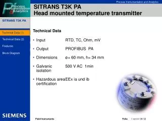
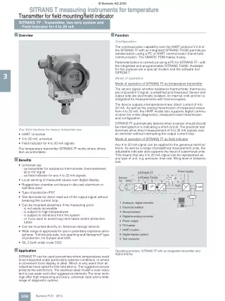
© Siemens AG 2009 SITRANS T measuring instruments for temperature Transmitter for field mounting/field indicator SITRANS TF - Transmitter, two-wire system and - Field indicator for 4 to 20 mA ■ Overview ■ Function Configuration The communication capability over the HART protocol V 5.9 of the SITRANS TF with an integrated SITRANS TH300 permits pa- rameterization using a PC or HART communicator (hand-held communicator). The SIMATIC PDM makes it easy. Parameterization is carried out using a PC for SITRANS TF - with the integrated and programmable SITRANS TH200. Available for this purpose are a special modem and the software tool SIPROM T. 3 Mode of operation Mode of operation of SITRANS TF as temperature transmitter The sensor signal, whether resistance thermometer, thermocou- ple or Ω and/or V signal, is amplified and linearized. Sensor and output side are electrically isolated. An internal cold junction is integrated for measurements with thermocouples. The device outputs a temperature-linear direct current of 4 to 20 mA. As well as the analog transmission of measured values from 4 to 20 mA, the HART model also supports digital commu- nication for online diagnostics, measured value transmission and configuration. SITRANS TF automatically detects when a sensor should should be interrupted or is indicating a short-circuit. The practical test terminals allow direct measurement of 4 to 20 mA signals over an ammeter without interrupting the output current loop. Mode of operation of SITRANS TF as field indicator Our field devices for heavy industrial use • HART, Universal • 4 to 20 mA, universal • Field indicator for 4 to 20 mA signals The temperature transmitter SITRANS TF works where others feel uncomfortable. Any 4 to 20 mA signal can be applied to the generous terminal block. As well as a range of predefined measurement units, the adjustable indicator also supports the input of customized units. This means that any 4 to 20 mA signal can be represented as any type of unit, e.g. pressure, flow rate, filling level or tempera- ture. ■ Benefits • Universal use - as transmitter for resistance thermometer, thermoelement, Ω or mV signal - as field indicator for any 4 to 20 mA signals • Local sensing of measured values over digital display • Rugged two-chamber enclosure in die-cast aluminium or stainless steel • Type of protection IP67 • Test terminals for direct read-out of the output signal without breaking the current loop • Can be mounted elsewhere if the measuring point - is not easily accessible - is subject to high temperatures - is subject to vibrations from the system - or if you want to avoid long neck tubes and/or protective tubes • Can be mounted directly on American-design sensors • Wide range of approvals for use in potentially explosive atmo- spheres. "Intrinsically safe, non-sparking and flameproof" type of protection, for Europe and USA. • SIL 2 (with order code C20) Power supply SITRANS TF Sensor TC SITRANS TH300 1 2 0000 00°C 8 RTD 5 3 4 9 D A µP Load D A 7 6 1 Analog-to- digital converter 2 Electrical isolation 3 Microprocessor 4 Digital-to-analog converter 5 Power supply 6 PC/Laptop 7 HART modem 8 Digital display (option) 9 Test connector Operating principle: SITRANS TF with an integrated transmitter and digital display ■ Application SITRANS TF can be used everywhere where temperatures need to be measured under particularly adverse conditions, or where a convenient local display is ideal. Which is why users from all industries have opted for this field device. The rugged enclosure protects the electronics. The stainless steel model is even resis- tant to sea water and other aggressive elements The inner work- ings offer high measuring accuracy, universal input and a wide range of diagnostic options. 3/58 Siemens FI 01 · 2010
© Siemens AG 2009 SITRANS T measuring instruments for temperature Transmitter for field mounting/field indicator SITRANS TF - Transmitter, two-wire system and - Field indicator for 4 to 20 mA ■ Technical specifications Input Resistance thermometer Measured variable Sensor type • to IEC 60751 • to JIS C 1604; a=0.00392 K-1 • to IEC 60751 Units Connection • Normal connection Parameterizable (see table "Digital measuring errors") 5 ... 25 Ω (see table "Digital mea- suring errors") Resistance-linear or special char- acteristic Measuring range Min. measured span Temperature Characteristic Pt25 ... Pt1000 Pt25 ... Pt1000 Ni25 ... Ni1000 °C and °F Thermocouple Measured variable Sensor type (thermocouples) • Type B • Type C • Type D • Type E • Type J • Type K • Type L • Type N • Type R • Type S • Type T • Type U Units Connection • Standard connection • Generation of average value • Generation of difference Temperature 3 Pt30Rh-Pt6Rh to DIN IEC 584 W5 %-Re to ASTM 988 W3 %-Re to ASTM 988 NiCr-CuNi to DIN IEC 584 Fe-CuNi to DIN IEC 584 NiCr-Ni to DIN IEC 584 Fe-CuNi to DIN 43710 NiCrSi-NiSi to DIN IEC 584 Pt13Rh-Pt to DIN IEC 584 Pt10Rh-Pt to DIN IEC 584 Cu-CuNi to DIN IEC 584 Cu-CuNi to DIN 43710 °C or °F 1 resistance thermometer (RTD) in 2-wire, 3-wire or 4-wire system Series or parallel connection of several resistance thermometers in a two-wire system for the genera- tion of average temperatures or for adaptation to other device types 2 resistance thermometers (RTD) in 2-wire system (RTD 1 – RTD 2 or RTD 2 – RTD 1) • Generation of average value • Generation of difference Interface • Two-wire system Parameterizable line resistance ≤ 100 Ω (loop resistance) No balancing required No balancing required ≤ 0.45 mA ≤ 250 ms for 1 sensor with open- circuit monitoring Can be switched off Can be switched off (value is adjustable) Parameterizable (see table "Digital measuring errors") 10 °C (18 °F) Temperature-linear or special char- acteristic • Three-wire system • Four-wire system Sensor current Response time 1 thermocouple (TC) 2 thermocouples (TC) 2 thermocouples (TC) (TC 1 – TC 2 or TC 2 – TC 1) ≤ 250 ms for 1 sensor with open- circuit monitoring Can be switched off Open-circuit monitoring Short-circuit monitoring Response time Open-circuit monitoring Cold junction compensation • Internal Measuring range With integrated Pt100 resistance thermometer With external Pt100 IEC 60571 (2-wire or 3-wire connection) Cold junction temperature can be set as fixed value Parameterizable (see table "Digital measuring errors") Min. 50 ... 100 °C (90 ... 180 °F) (see table "Digital measuring errors") Temperature-linear or special char- acteristic Min. measured span Characteristic • External Resistance-based sensors Measured variable Sensor type Units Connection • Normal connection • External fixed Actual resistance Resistance-based, potentiometers Ω Measuring range Min. measured span 1 resistance-based sensor (R) in 2-wire, 3-wire or 4-wire system 2 resistance-based sensors in 2-wire system for generation of average value 2 resistance-based sensor in 2-wire system (R 1 – R 2 or R 2 – R 1) Characteristic • Generation of average value mV Sensor Measured variable Sensor type DC voltage DC voltage source (DC voltage source possible over an externally connected resistor) mV ≤ 250 ms for 1 sensor with open- circuit monitoring Can be switched off Can be switched off (value is adjustable) -10 ... +70 mV -100 ... +1100 mV 2 mV or 20 mV -1.5 ... +3.5 V DC ≥ 1 MΩ Voltage-linear or spec. characteristic • Generation of difference Interface • Two-wire system Units Response time Parameterizable line resistance ≤ 100 Ω (loop resistance) No balancing required No balancing required ≤ 0.45 mA ≤ 250 ms for 1 sensor with open- circuit monitoring Can be switched off Can be switched off (value is adjustable) • Three-wire system • Four-wire system Sensor current Response time Open-circuit monitoring Short-circuit monitoring Measuring range Min. measured span Overload capacity of the input Input resistance Characteristic Open-circuit monitoring Short-circuit monitoring 3/59 Siemens FI 01 · 2010
© Siemens AG 2009 SITRANS T measuring instruments for temperature Transmitter for field mounting/field indicator SITRANS TF - Transmitter, two-wire system and - Field indicator for 4 to 20 mA Output Output signal Communication with SITRANS TH300 Digital display Digital display (optional) Display Digit height Display range Units Setting: Zero point, upper range value and unit Load voltage Measuring accuracy Digital measuring errors Reference conditions • Auxiliary power supply • Load • Storage temperature • Warming-up time Error in the analog ouput (digital/analog converter) Error due to internal cold junction Temperature effect Power supply effect Effect of load impedance Long-term drift • in the first month • after one year • after 5 years Rated conditions Ambient temperature Storage temperature Condensation Electromagnetic compatibility Certificate and approvals Explosion protection ATEX • "Intrinsically-safe" type of protection 4 ... 20 mA, 2-wire to HART Rev. 5.9 With digital indicator: II 2 (1) G EEx ia IIC T4 Without digital indicator: II 2 (1) G EEx ia IIC T6 ZELM 99 ATEX 0007 II 3G EEx nAL IIC T6/T4 in current loop max. 5 digits 9 mm (0.35") -99999 ... +99999 Any (max. 5 char.) With 3 keys - EC type test certificate • "Operating equipment that is non-sparking and has limited en- ergy for zone 2" type of protection - EC type test certificate • Flame-proof enclosure" type of protection - EC type test certificate Explosion protection to FM • Identification (XP, DIP, NI, S) 3 ZELM 99 ATEX 0007 II 2 G EEx d IIC T5/T6 CESI 99 ATEX 079 Certificate of Compliance 3017742 • XP / I / 1/BCD / T5 Ta = 85 °C (185 °F), T6 Ta = 50 °C (112 °F), Type 4X • DIP / II, III / 1 / EFG / T5 Ta = 85 °C (185 °F), T6 Ta = 50 °C (112 °F), Type 4X • NI / I / 2 / ABCD / T5 Ta = 85 °C (185 °F), T6 Ta = 50 °C (112 °F), Type 4X • S / II, III / 2 / FG / T5 Ta = 85 °C (185 °F), T6 Ta = 50 °C (112 °F), Type 4X 2.1 V See table "Dig. measuring errors" 24 V ± 1 % 500 Ω 23 °C (73.4 °F) > 5 min < 0.025 % of span Hardware and software require- ments • For the parameterization software SIPROM T for SITRANS TH200 - Personal computer < 0.5 °C (0.9 °F) < 0.1 % of max. span/10 °C (18 °F) < 0.001 % of span/V < 0.002 % of span/100 Ω PC with CD-ROM drive and USB/RS 232 interface Windows 98, NT, 2000, XP See chapter 9, "Software", "SIMATIC PDM" - PC operating system • For the parameterization software SIMATIC PDM for SITRANS TH300 Communication Load for HART connection • Two-core shielded • Multi-core shielded Protocol < 0.02 % of max. span < 0.2 % of max. span < 0.3 % of max. span 230 ... 1100 Ω ≤ 3.0 km (1.86 mi) ≤ 1.5 km (0.93 mi) HART protocol, version 5.x -40 ... +85 °C (-40 ... +185 °F) Permissible According to EN 61326 and NAMUR NE21 IP67 Factory setting (transmitter): • Pt100 (IEC 751) with three-wire circuit • Measuring range: 0 ... 100 °C (32 ... 212 °F) • Fault current 22.8 mA • Sensor offset: 0 °C (0 °F) • Damping 0.0 s Degree of protection to EN 60529 Design Approx. weight Approx. 1.5 kg (3.3 lb), without options See "Dimensional drawings" Die-cast aluminum, low in copper, GD-AlSi 12 or stainless steel, poly- ester-based lacquer, stainless steel rating plate Screw terminals, cable inlet via M20 x 1.5 or ½-14 NPT threaded gland Steel, galvanized and chrome- plated or stainless steel Dimensions Enclosure material Electrical connection, sensor connection Mounting bracket (optional) Power supply Without digital display 11 ... 35 V DC (30 V with Ex) With digital display Electrically isolated • Test voltage 13.1 ... 35 V DC (30 V with Ex) Between input and output Ueff = 1 kV, 50 Hz, 1 min 3/60 Siemens FI 01 · 2010
© Siemens AG 2009 SITRANS T measuring instruments for temperature Transmitter for field mounting/field indicator SITRANS TF - Transmitter, two-wire system and - Field indicator for 4 to 20 mA Digital measuring errors Resistance thermometer Input Thermocouple elements Input Measuring range Min. mea- sured span °C Digital accuracy °C Measuring range °C(°F) 0 ... 1820 (32 ... 3308) 0 ... 2300 (32 ... 4172) 0 ... 2300 (32 ... 4172) -200 ... +1000 (-328 ... +1832) -210 ... +1200 (-346 ... +2192) -230 ... +1370 (-382 ... +2498) -200 ... +900 (-328 ... +1652) -200 ... +1300 (-328 ... +2372) -50 ... +1760 (-58 ... +3200) -50 ... +1760 (-58 ... +3200) -200 ... +400 (-328 ... +752) -200 ... +600 (-328 ... +1112) Min. measured span °C 100 Digital accuracy °C 21) °C (°F) (°F) (°F) (°F) (180) (°F) (3.60)1) according to IEC 60751 Pt25 Type B -200 ... + 850 (-328 ... +1562) -200 ... + 850 (-328 ... +1562) -200 ... + 850 (-328 ... +1562) -200 ... + 850 (-328 ... +1562) -200 ... + 350 (-328 ... +662) 10 (18) 0,2 (0.36) Type C (W5) 100 (180) 2 (3.60) 12) (1.80)2) Pt50 10 (18) 0,15 (0.27) Type D (W3) 100 (180) 3 Pt100 ... Pt200 10 (18) 0,1 (0.18) Type E 50 (90) 1 (1.80) Pt500 10 (18) 0,15 (0.27) Type J 50 (90) 1 (1.80) 10 (18) 0,15 (0.27) 50 (90) 1 (1.80) Pt1000 Type K according to JIS C1604-81 Pt25 Type L 50 (90) 1 (1.80) -200 ... + 649 (-328 ... +1200) -200 ... + 649 (-328 ... +1200) -200 ... + 649 (-328 ... +1200) -200 ... + 649 (-328 ... +1200) -200 ... + 350 (-328 ... +662) -60 ... + 250 (-76 ... +482) 10 (18) 0,2 (0.36) Type N 50 (90) 1 (1.80) Pt50 10 (18) 0,15 (0.27) Type R 100 (180) 2 (3.60) Pt100 ... Pt200 10 (18) 0,1 (0.18) Type S 100 (180) 2 (3.60) Pt500 10 (18) 0,15 (0.27) Type T 40 (72) 1 (1.80) Pt1000 10 (18) 0,15 (0.27) Type U 50 (90) 2 (3.60) Ni 25 ... Ni1000 10 (18) 0,1 (0.18) 1)The digital accuracy in the range 0 to 300 °C (32 to 572 °F) is 3 °C (5.4 °F). 2)The digital accuracy in the range 1750 to 2300 °C (3182 to 4172 °F) is 2 °C (3.6 °F). Resistance-based sensors Input mV sensors Input Measuring range Min. mea- sured span Ω 5 25 Digital accuracy Ω 0,05 0,25 Measuring range Min. mea- sured span mV 2 20 Digital accuracy µV 40 400 Ω 0 ... 390 0 ... 2200 Resistance Resistance mV -10 ... +70 -100 ... +1100 mV sensors mV sensors The digital accuracy is the accuracy after the analog/digital conversion including linearization and calculation of the mea- sured value. An additional error is generated in the output current 4 to 20 mA as a result of the digital/analog conversion of 0.1 % of the set span (digital-analog error). The total error under reference conditions at the analog output is the sum from the digital error and the digital-analog error (poss. with the addition of cold junction errors in the case of thermocou- ple measurements). 3/61 Siemens FI 01 · 2010
© Siemens AG 2009 SITRANS T measuring instruments for temperature Transmitter for field mounting/field indicator SITRANS TF - Transmitter, two-wire system and - Field indicator for 4 to 20 mA ■ Dimensional drawings 80 (3.15) 100* (3.94) 144 (5.67) 138* (5.43) 13 (0.51) 15* (0.59) 55 (2.17) b (0.79) 28 52 (2.05) 50* (1.97) 2 6 20 (1.10) (1.97) 50 80 (3.15) 117 (4.61) 3 3 a 237 (9.33) 4 8 5 68 (2.68) 120 (4.72) 1 36,5 (1.44) 72 (2.83) a: max. 164 (6.46) (M20x1.5) max. 189 (7.44) (½-14 NPT) b: max. 25 (0.98) (M20x1.5) max. 50 (1.97) (½-14 NPT) 123 (4.84) *) Dimensions for stainless steel enclosure 7 Æ 50 ... 60 (1.97 ... 2.36) 105 (4.13) 1 Sensor connection (screwed gland M20x1,5 or ½-14 NPT) 6 Protective cover (without function) 2 Blanking plug 7 Mounting bracket (option) with clamp for securing to a vertical or horizontal pipe 3 Electrical connection (screwed gland M20x1,5 or ½-14 NPT) 4 Terminal side, output signal 8 Cover with window for digital display 5 Terminal side, sensor SITRANS TF, dimensions in mm (inches) 3/62 Siemens FI 01 · 2010
© Siemens AG 2009 SITRANS T measuring instruments for temperature Transmitter for field mounting/field indicator SITRANS TF - Transmitter, two-wire system and - Field indicator for 4 to 20 mA Selection and Ordering data Selection and Ordering data Order No. Order No. D) 7 NG 3 1 3 7 - 77777 Temperature transmitter in field housing Two-wire system 4 ... 20 mA, with electrical isolation, with documentation on CD-ROM Integrated transmitter • SITRANS TH200, programmable - without Ex protection - with EEx ia - with EEx nAL for zone 2 - total device SITRANS TF EEx d1) - total device SITRANS TF according to FM (XP, DIP, NI, S)1) • SITRANS TH300, communication capability according to HART V 5.9 - without Ex-protection - with EEx ia - with EEx nAL for zone 2 - total device SITRANS TF EEx d1) - total device SITRANS TF according to FM (XP, DIP, NI, S)1) SITRANS TF field indicator for 4 ... 20 mA signals, with documentation on CD-ROM • without Ex-protection • with EEx ia • with EEx nAL for zone 2 • total device SITRANS TF EEx d1) • total device SITRANS TF according to FM (XP, DIP, NI, S)1) Enclosure • die-cast aluminium • stainless steel precision casting Connections/cable inlet • screwed glands M20x1.5 • screwed glands ½-14 NPT Digital indicator • without • with Mounting bracket and securing parts • without • made of steel • made of stainless steel Further designs Please add "-Z" to Order No. and specify Order code(s) and plain text. Customer-specific setting of operating data Inscription on measuring-point label • measuring range (max. 27 characters) • meas. point description (max. 16 char.) • measuring point text (max. 27 char.) Test protocol (5 measuring points) SIL 2 (functional safety) Power supply units see "SITRANS I supply units and input isolators". Accessories Modem for SITRANS TH200 incl. parameterization software T • with USB interface } C) } C) } A5E00364512 7NG3092-8KU • with RS 232 interface 7NG3092-8KM 5 5 5 5 5 0 1 2 4 5 CD for measuring instruments for temperature with documentation in German, English, French, Spanish, Italian and Portuguese, and parameterization software SIPROM T (included in delivery with SITRANS TF) HART modem • with RS 232 interface 3 6 6 6 6 6 0 1 2 4 5 } D) } D) 7MF4997-1DA • with USB interface 7MF4997-1DB SIMATIC PDM parameterization software also for SITRANS TH300 Mounting bracket and securing parts • made of steel for 7NG313.-..B.. • made of steel for 7NG313.-..C.. • made of stainless steel for 7NG313.-..B.. • made of stainless steel for 7NG313.-..C.. Digital indicator1) Connection board } Available ex stock. Power supply units see "SITRANS I supply units and input isolators". see chap. 9 7 NG 3 1 3 7 - 77777 7MF4997-1AC 7MF4997-1AB } 7MF4997-1AJ 7MF4997-1AH 7MF4997-1BS A5E02226423 0 0 0 0 0 0 1 2 4 5 1 1 1 1 1 A E 1)It is not possible to upgrade devices with Ex protection C) Subject to export regulations AL: N, ECCN: EAR99. D) Subject to export regulations AL: N, ECCN: EAR99H. B C 0 1 Factory setting (transmitter): • Pt100 (IEC 751) with three-wire circuit • Measuring range: 0 ... 100 °C (32 ... 212 °F) • Fault current 22.8 mA • Sensor offset: 0 °C (0 °F) • Damping 0.0 s 0 1 2 Order code Y012) Y223) Y233) Y243) C114) C 2 05) 1)Without cable gland. 2)Y01: Please specify all data that does not correspond to factory settings (see above) (e.g. Y01 = thermocouple element type K; internal cold junc- tion; 0 ... 800 °C; fault current 3.6 mA). 3)Y22, Y23, Y24: If no order is placed for Y01, these data are only noted on the measuring point label and are not programmed in the transmitter. 4)Can only be ordered together with Y01. 5)Only with 7NG3135-... and 7NG3136-... 3/63 Siemens FI 01 · 2010
© Siemens AG 2009 SITRANS T measuring instruments for temperature Transmitter for field mounting/field indicator SITRANS TF - Transmitter, two-wire system and - Field indicator for 4 to 20 mA ■ Schematics Thermocouple Resistance thermometer Resistance 3 Cold junction compensation Internal/fixed value Two-wire system 1) Two-wire system 1) Cold junction compensation with external Pt100 in two-wire system 1) Three-wire system Three-wire system Cold junction compensation with external Pt100 in three-wire system Four-wire system Four-wire system Generation of average value / difference with internal cold junction compensation Generation of average value / difference 1) Generation of average value / difference 1) 1) Programmable line resistance for the purpose of correction. Voltage measurement Current measurement SITRANS TF, sensor connection assignment 3/64 Siemens FI 01 · 2010