Download
1 / 54
540 likes | 670 Vues
This presentation details the development of a high-speed digital transmitter module within a quantum encryption system, focusing on the BB84 protocol for secure communication. The project aims to generate a 0.5ns electrical pulse at 4V to activate a laser diode for data transmission. The presentation features an overview of system components, design modifications employing ECL technology, and validation through HyperLynx simulations. The objective is foundational in utilizing encryption methods that exploit quantum mechanics, ensuring safe transmission of confidential information.

E N D
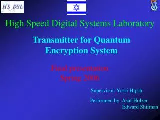
High Speed Digital Systems Laboratory Transmitter for Quantum Encryption System Final presentation Spring 2006 Supervisor: Yossi Hipsh Performed by: Asaf Holzer Edward Shifman
Background Several methods can be used for encrypting information. One of them is the BB84 scheme, which was developed by Brassard & Bennett. The advantage of this method is that it is impossible to crack it, because it is based on the “No Cloning” principle. The BB84 scheme was mathematically proved as a perfectly safe Method, in a theoretical perfect world without noises.
Project Objectives • The transmitter module is part of a complex system, which • purpose is to send a digital code, which will later be used as • key for encrypting and decrypting information. • Our goal is to produce an electrical pulse which is ~0.5ns • wide and its magnitude is 4v. The purpose of this pulse is to • activate the laser diode.
The Overall System Block Diagram Computer + Labview Computer + Counter Synchronization Transmitter Reciever Interferometers, etc.
Original Plan Pulse trigger monostable D.D.L TTL 2 ECL ECL Programmable Delay Chip 1:2 And Gate ECL Programmable Delay Chip 1:2 Long fiber Bal_UN Bal_UN Gain Gain P_Quant P_Sync
Original Plan – continued… Pulse trigger monostable D.D.L TTL 2 ECL ECL Programmable Delay Chip 1:2 And Gate ECL Programmable Delay Chip 1:2 Long fiber Bal_UN Bal_UN Gain Gain Ref P_Stab
Some more advances In order to improve the module’s performance we decided to use ECL technology from the very beginning of the pulse module, so we put the TTL-ECL device at the beginning. We replaced the components so they will operate in 3.3 voltage level.
Plan #2 ECL Prog. Delay Chip Pulse trigger ECL Prog. Delay Chip 1:2 And Gate ECL Prog. Delay Chip … TTL 2 ECL Bal_UN P_Sync monostable Gain … 1:4 P_Sync P_Quant … Ref
Plan #3 Computer – LabView trig stab_en sync_ctrl counter 1:4 (TTL) sel sel Mux Mux 1:4 (TTL) TTL-ECL TTL-ECL TTL-ECL Pulse-Module Pulse-Module Pulse-Module P_Quant P_Stab P_Sync detector ref ref
The Monostable (ECL) – Take #1… MC100EP31 Flip Flop S Q ECL Prog. Delay Chip 1 1:4 (ECL) D R Q ECL Prog. Delay Chip 2 CLK ECL Prog. Delay Chip 3 MC100EP31 Characteristics:
The Monostable Timing Diagram Data t CLK ts t Reset t Q tR-Q tclk-Q t Q Min. Pulse width: 530ps 130ps 400ps
Plan #3 – Pulse Module 10ns Bal_UN Gain 3ns 0.5ns monostable monostable 1:2 Bal_UN Gain And Gate ref Plan B
Plan #3 – Pulse Module 3ns S Flip Flop Q 1:4 (ECL) D Q CLK ECL Prog. Delay Chip 1 R ECL Prog. Delay Chip 2 0.5ns S Flip Flop Q 1:4 (ECL) D ECL Prog. Delay Chip 3 CLK ECL Prog. Delay Chip 4 R Q ECL Prog. Delay Chip 5 And Gate 0.5ns
Voltage Surfaces • Vcc - 3.3V • Vtt – 1.3V • GND We ended up with one voltage source of 3.3V. Using a regulator to get 1.3V and a DC/DC converter to get 5V.
Vtt=1.3v Vtt=1.3v The Original Bal-UN OUT + IN 140Ω 140Ω - 68Ω 68Ω 68Ω 68Ω 150Ω 100nF 1nF 150Ω 1nF 100nF
The Final Bal-UN OUT + IN 140Ω 140Ω - 68Ω 68Ω 68Ω 68Ω Vtt=1.3v
The Final ORCAD Design: Pulse-Module:
The Final ORCAD Design Test Points: • Counter_tp – The detector has detected p_quan. • Splitter14_tp – A pulse trigger has been received. • Quan_tp • Stab_tp • Sync_tp Testing each Pulse Module
Connectors • Power Connector • SMA Connector • Flat-Cable Connector
Stack & Lines Design: Raw material used – Fr4 W = 7mil Calculated using Microstrip equations, to achieve
Stack & Lines Design: Raw material used – Fr4 W = 7mil Calculated using Stripline equations, to achieve
HyperLynx Simulation First Assuming
HyperLynx Simulation Simulation Results for various frequencies @500MHz @2000MHz
HyperLynx Simulation Falling Edge Simulation
HyperLynx Simulation Simulation Results for various frequencies Now Assuming @500MHz @2000MHz Delay =
HyperLynx Simulation Simulation until now using S – distance between the lines Field Influence @ S=8mil Field Influence @ S=20mil
HyperLynx Simulation - Vias HyperLynx does not support Vias, so we had to model the via, using a capacitor & a resistor.
HyperLynx Simulation - Vias Simulation results for various frequencies @500MHz @1000MHz
HyperLynx Simulation - Vias Running a simulation without modeling the vias (with same total length of the transmission line) @500MHz @1000MHz
HyperLynx Simulation - Conclusion • Impedance Coordination & Reflections • Delays • Crosstalk • Via’s influence
The FPGA Field Programmable Gate Array
FPGA Design Opcode structure: Edit Mode: Mode (1bit) Pulse_editmode (2bit) Pulse_width (10bit) Pulse_offset (11bit) 0 Work Mode: Mode (1bit) Pulse_workmode (3bit) 1
The FPGA – VHDL Design Delay 2 Delay Decode LEN Delay 1 LEN offset_temp <= pulse_offset - const_440; PROCESS(clk) BEGIN if (offset_temp(10) = '1') then first_offset <= const_1023; second_offset <= offset_temp(9 downto 0) + "0000000001"; else first_offset <= offset_temp(9 downto 0); second_offset <= const_0; end if; END PROCESS; delay1 <= first_offset; delay2 <= second_offset; delay3 <= second_offset +const_450- pulse_width; Delay 3 LEN